skoda Workshop Repair Guides

Skoda Workshop Service and Repair Manuals

Test air mass meter - valid ? 07.97 > < Test injection valves - valid 08.97 ?
Test fuel pump relay and control
Special tools and workshop equipment required
t  Test box -V.A.G 1598/22-
t  Handheld multimeter (e.g. -V.A.G 1526 A-)
t  Voltage tester (e.g. - V.A.G 1527-)
t  Measuring tool set (e.g. -V.A.G 1594 A-)
t  Current flow diagram
Test conditions
l  The fuse 132 in fuse holder on battery must be O.K.
  Note
   
The fuel pump relay is located on the relay carrier in the interior of the vehicle on the driver side behind the storage compartment in the footwell; replay position 4.
A - Testing fuel pump relay-J17-
–  Remove storage in front left of footwell.
  S24-0181
–  Take fuse 28 out of the fuse holder and connect the voltage tester between earth and one of the two contacts for fuse 28 in the fuse holder.
–  Switch on the starter motor for a short time.
The fuel pump relay must close (be felt and audible); the voltage tester must light up.
–  If the voltage tester does not light up, although the fuel pump relay has been connected, repeat the test on the second contact.
  S24-0182
–  If the voltage tester still does not light up, test the wiring between the contact 23 (relay position 4) and the fuse 28 for continuity or eliminate the open circuit → Current Flow Diagrams, Fault Finding Electrics, Fitting Locations.
–  If no open circuit was detected, replace the fuel pump relay.
–  If the fuel pump relay does not connect, test control → Anchor.
–  If the power supply and the control is o.k., replace the fuel pump relay.
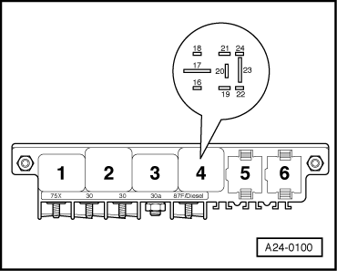
B - Test voltage supply and control of the fuel pump relay
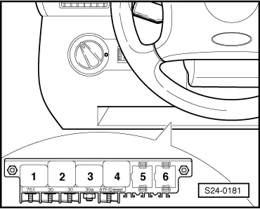
–  Pull the fuel pump relay -J17- out of the relay carrier, relay position 4.
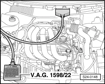
Checking voltage supply
–  Switch on ignition.
  WARNING
To avoid damaging the electronic components, switch on the relevant measuring range before connecting the measuring cables and comply with the test conditions.
  A24-0100
–  Connect hand multimeter -V.A.G 1526 - consecutively to contact 19 (positive) and earth as well as to 17 (positive) and earth of the relay base.
Specified value: approx. battery voltage
–  If the nominal values are not reached, eliminate line interruption → Current Flow Diagrams, Fault Finding Electrics, Fitting Locations.
Test control
  A24-0100
–  Connect voltage tester -V.A.G 1527- to contact 16 (earth) and positive.
–  The voltage tester must light up when operating the starter.
  Note
The voltage tester with low power consumption does not go out fully but remains slightly lit until the starter is operated.
If the voltage tester does not light up, test wiring as follows:
  A24-0100
–  Connect test box -V.A.G 1598/22 - at wiring loom to the engine control unit.
–  Connect hand multimeter between contact 16 of relay base and socket 4 of the test box and test wiring for continuity.
–  Eliminate line interruption if necessary → Current Flow Diagrams, Electrical Fault Finding, Fitting Locations
–  If there is no open circuit and the voltage tester does not light up - replace the engine control unit → Chapter.
–  If the control of the fuel pump relay as well as the wiring is o.k. - replace the fuel pump relay.
–  Insert fuese 28.
  S24-0148

Test air mass meter - valid ? 07.97 > < Test injection valves - valid 08.97 ?