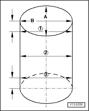
skoda Workshop Repair Guides

Skoda Workshop Service and Repair Manuals

Checking piston projection in TDC > < Removing and installing the sealing flange on the belt pulley side
Disassembling and assembling pistons and conrods
1 - Piston rings
–  Offset joint 120°
–  use piston ring pliers for removing and installing
–  Marking “TOP” faces piston crown
–  Inspect gap clearance → Fig.
–  Inspect end clearance → Fig.
2 - Piston
–  with combustion chamber
–  mark installation position and matching cylinder
–  Installation position and assignment of piston/cylinder → Fig.
–  arrow on piston crown faces towards the belt pulley
–  use piston ring tensioning strap for installing
–  replace piston if there is any sign of crack formation on the piston body
–  inspect piston projection at TDC → Chapter
–  Ø Piston = 79.47 mm
3 - Piston pin
–  if stiff, heat piston to 60°C
–  removing and installing with -MP 3-400-
4 - Circlip
5 - Conrod
–  always replace as a set only
–  mark matching cylinder -A-
–  Fitting position: Markings -B- point towards the belt pulley side
6 - Bearing shell
–  pay attention to correct installation position
–  do not mix up used bearing shells
–  ensure tightly located in retaining lugs
–  Axial play wear limit: 0.37 mm
7 - Cylinder block
–  inspect cylinder bore → Fig.
–  Ø Cylinder = 79.51 mm
8 - Conrod bearing cap
–  mark matching cylinder -A-
–  Fitting position: Markings -B- point towards the belt pulley side
9 - Oil injection nozzle
–  for piston cooling
10 - 25 Nm
–  with the overpressure valve
–  replace without sealant
11 - 30 Nm + torque a further 1/4 turn (90°)
–  replace
–  Oil thread and contact surface
  S13-0367
Inspecting piston ring gap clearance
Special tools and workshop equipment required
t  Feeler gauge
Test sequence
–  Push in ring at right angles to the cylinder wall from the top through to the bottom cylinder opening, about 15 mm from the cylinder edge.
  V13-0016
Piston ring
dimensions in mm
newWear limit
1. Compression ring0,20...0,401,0
2. Compression ring0,20...0,401,0
Oil scraper ring0,25...0,501,0

   
Inspect piston ring end clearance
Special tools and workshop equipment required
t  Feeler gauge
–  Clean before inspecting the annular groove of the piston.
  V13-0687
Piston ring
dimensions in mm
newWear limit
1. Compression ring0,06...0,090,25
2. Compression ring0,05...0,080,25
Oil scraper ring0,03...0,060,15

   
Inspecting cylinder bore
Special tools and workshop equipment required
t  Internal fine measuring instrument 50...100 mm
Test sequence
–  Measure cylinder at 3 points crosswise in transverse direction -A- and lengthwise -B-.
t  Variations compared to nominal dimension max. 0.10 mm
  Note
Do not measure the cylinder bore if the cylinder block is fixed to the assembly stand with the engine and gearbox mount -MP 1-202 -, as this may result in incorrect measurements.
  V13-0280
Piston fitting position and assignment of the piston/cylinder
Special tools and workshop equipment required
t  Electric stylus
Work procedure
–  Mark the fitting position and assignment on the piston inner side (not on the piston crown) using an electric stylus or a marker.
Pistons in cylinders 1 and 2:
Large piston relief for inlet valve to flywheel side -arrows-.
Pistons in cylinders 3 and 4:
Large piston relief for inlet valve to belt pulley side -arrows-.
  Note
t  For new pistons the cylinder assignment is colour-coded on the piston crown.
t  Piston of cylinder 1 and 2: Marking 1/2
t  Piston of cylinder 3 and 4: Marking 3/4
  V13-1204

Checking piston projection in TDC > < Removing and installing the sealing flange on the belt pulley side