
Octavia Mk1
| Repairing Valve Gear |
 Note
Note| t | Cylinder heads with cracks between the valve seats may continue to be used without any reduction in life provided these are slight incipient cracks which are not more than 0.5 mm wide. |
| t | After installing the camsaft, the engine must not be started for about 30 minutes. The hydraulic bucket tappets must settle (otherwise valves would strike the pistons). |
| t | After carrying out work on the valve gear, carefully crank engine at least 2 revolutions to ensure that no valve touches the piston when the engine is started. |
| t | Always replace gasket rings and seals. |
| t | Removing and installing the tandem pump → Chapter. |

| 1 - | 20 Nm + torque a further 90° (1/4 turn) |
| q | replace |
| q | Pay attention to order when slackening and tightening → 1.9-ltr./74 kW (TDI) - Engine, Fuel Injection and Glow Plug System; Rep. Gr.23 |
| 2 - | Rocker arm support |
| q | with rocker arms |
| q | do not mix up (mark) |
| q | removing and installing → 1.9-ltr./74 kW (TDI) Engine - Fuel Injection and Glow Plug System; Rep. Gr.23 |
| 3 - | Cylinder head bolt |
| q | replace |
| q | pay attention to sequence for loosening and tightening → Chapter |
| q | before installing, insert washers → Item into the cylinder head |
| 4 - | Washer |
| q | for cylinder head screws |
| q | before installing the bearing caps → Item insert into the cylinder head |
| 5 - | Bucket tappets |
| q | do not interchange |
| q | with hydraulic valve clearance compensation |
| q | check → Chapter |
| q | before removing remove the camshaft bearing shells |
| q | lay aside with contact surface facing down |
| q | oil contact surfaces |
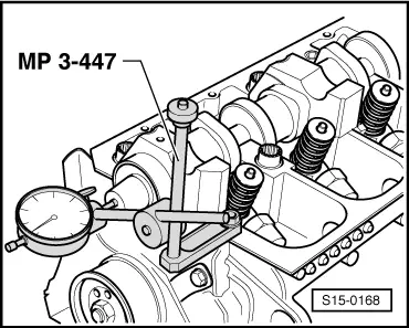
| q | before installing check axial play of the camshaft → Fig. |
| 6 - | Valve collet |
| 7 - | Valve spring retainer |
| 8 - | Valve spring outside |
| q | removing and installing → Chapter |
| 9 - | Valve spring inside |
| q | removing and installing → Chapter |
| 10 - | Valve stem seal |
| q | replace → Chapter |
| 11 - | Valve guide |
| q | check → Chapter |
| q | if the wear limit is exceed, replace cylinder head |
| 12 - | Unit injector |
| q | removing and installing → 1.9-ltr./74 kW (TDI) Engine - Fuel Injection and Glow Plug System; Rep. Gr.23 |
| 13 - | Cylinder head |
| q | pay attention to the notes → Anchor |
| q | reworking valve seats → Chapter |
| q | removing and installing → Chapter |
| 14 - | Gasket ring |
| q | Do not apply additional oil to sealing lips |
| q | before installing, remove with a clean cloth oil residues from camshaft studs |
| q | before fitting on, fix in place the groove at the camshaft cone with adhesive tape (e. g. with Sellotape) |
| q | removing and installing → Chapter |
| 15 - | Valves |
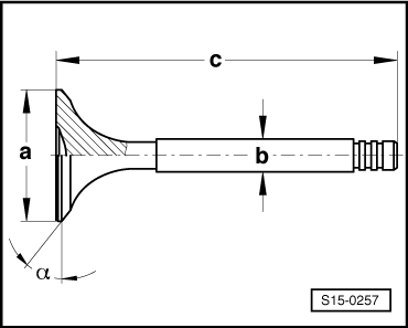
| q | Pay attention to the part number |
| q | Valve dimensions → Fig. |
| q | do not rework; only grinding in with grinding paste in the valve seat is permissible. |
| 16 - | Bearing shell |
| q | do not mix up used bearing shells (mark) |
| q | ensure the retaining lugs are correctly located in the bearing caps and in the cylinder head |
| 17 - | Camshaft |
| q | Pay attention to the part number |
| q | inspecting axial play → Fig. |
| q | removing and installing → Chapter |
| q | Slack: max. 0.04 mm |
| 18 - | Bearing caps |
| q | Observe the order of fitting → Chapter |
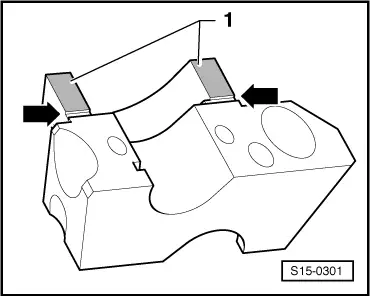
| q | seal contact surface of bearing caps 1 and 5 with sealant -AMV 174 004 01- → Fig. |
| 19 - | 8 Nm + torque a further 90° (1/4 turn) |
| q | replace |
Note
|
|
Note
|
|
| Dimension | Inlet valve | Exhaust valve | |
| Ø a | mm | 35,95 | 31,45 |
| Ø b | mm | 6,980 | 6,965 |
| c | mm | 89,95 | 89,55 |
| α | ∠° | 45 | 45 |
|
| Dimension | Inlet valve | Exhaust valve | |
| Ø a | mm | 35,95 | 31,45 |
| Ø b | mm | 6,980 | 6,965 |
| c | mm | 89,45 | 89,05 |
| α | ∠° | 45 | 45 |