
Octavia Mk1
| Removing and installing crankshaft |

| 1 - | Bearing shells 1, 2, 4 and 5 |
| q | for bearing cap without lubricating groove |
| q | for cylinder block with lubricating groove |
| q | do not mix up used bearing shells (mark) |
| 2 - | 65 Nm + torque a further 90° (1/4 turn) |
| q | replace |
| q | tighten thread |
| 3 - | Bearing caps |
| q | Bearing cap 1: on the belt pulley side |
| q | Bearing cap 3: with recesses for thrust washers |
| q | retaining lugs of the bearing shells of the cylinder block/bearing cap must be on top of one another |
| 4 - | Bearing shell 3 |
| q | for bearing cap without lubricating groove |
| q | for cylinder block with lubricating groove |
| 5 - | Thrust washer |
| q | for bearing cap 3 |
| q | pay attention to locating element |
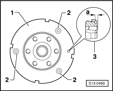
| 6 - | Pulse rotor |
| q | for engine speed sender -G28- |
| q | replace if damaged |
| q | replace each time the fixing bolts are slackened |
| q | Assembly only possible in one position - holes offset |
| q | removing and installing → Fig. |
| 7 - | 10 Nm + torque a further 90° (1/4 turn) |
| q | replace |
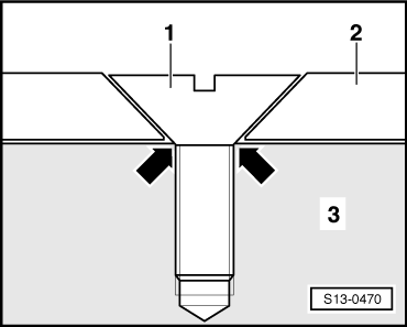
| 8 - | Fit pin |
| q | Checking projection from crankshaft → Fig. |
| 9 - | Crankshaft |
| q | Pay attention to the part number |
| q | with chain sprocket for oil pump drive |
| q | Crankshaft bearing journal: Ø 54.00 mm |
| q | Conrod bearing journal: Ø 47.80 mm |
| q | Axial play when new: 0.07...0.17 mm |
| q | Wear limit: 0.37 mm |
| 10 - | Thrust washer |
| q | for cylinder block, bearing 3 |
 Note
Note
|
|