| –
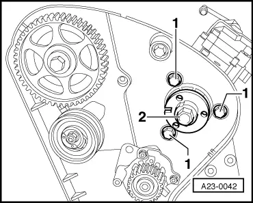
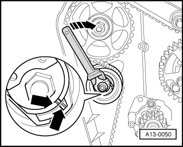
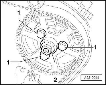
| Loosen fixing bolts -1- of the injection pump gear. |

Note | t
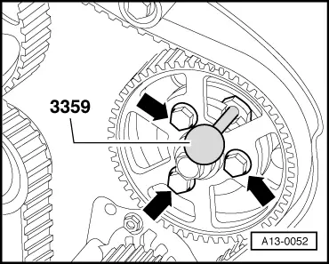
| Use rig pin -3359- to counterhold the injection pump gear → Anchor, fig A13-0052. |
| t
| Rig pin must be moistened with oil each time in use. It is recommended to use a mirror in order to facilitate the removal. |
| t
| If it is not possible to unlock the injection pump gear with the rig pin, the crankshaft must be turned in such a way that the bore holes for the rig pin are aligned. Then, loosen the screws of the injection pump gear and only then position the crankshaft to TDC. |
| t
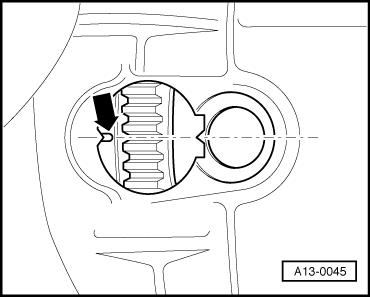
| Never release the central nut -2- of the injection pump gear. This could result in a misadjustment of the basic setting of the injection pump which can no longer be corrected with workshop tools. |
| –
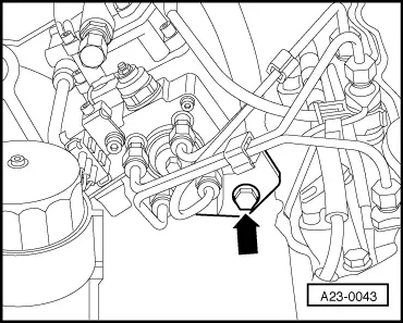
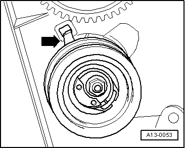
| Unscrew nut for tensioning pulley. |
| –
| Remove toothed belt from the camshaft sprockets and the injection pump gear. |
| –
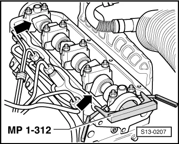
| Disconnect the plug connection for the electrical connections of the injection pump. |
|
|
|