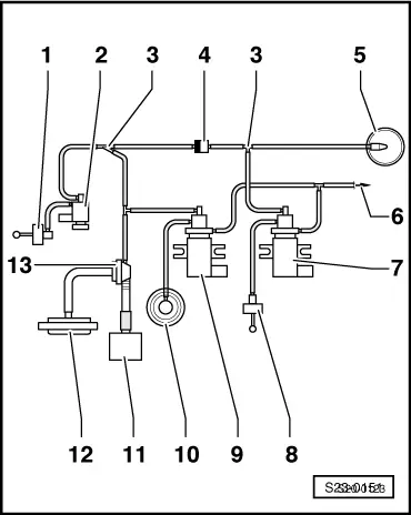
| Hose layout plan for intake manifold flap activation |
| 1 - | Mechanical exhaust gas recirculation valve |
| 2 - | Exhaust gas recirculation valve -N18- |
| 4 - | To the brake servo unit |
| 7 - | Vacuum setting element for intake manifold flap |
| 8 - | Changeover valve for intake manifold flap -N239- |
| 1 - | Vacuum setting element for intake manifold flap |
| 2 - | Changeover valve for intake manifold flap -N239- |
| –
| white connection points to charge pressure control solenoid valve -N75- |
| 7 - | Solenoid valve for charge pressure control -N75- |
| 8 - | Vacuum setting element |
| –
| for the charge pressure control valve |
| –
| Components of the exhaust gas turbocharger cannot be replaced individually |
| 9 - | Exhaust gas recirculation valve -N18- |
| 10 - | Mechanical exhaust gas recirculation valve |
|
|
|
