| Test the change-over valve for the intake manifold flap |
| Special tools and workshop equipment required |
| t
| Hand vacuum pump (e.g. -V.A.G 1390-) |
| t
| Test box -V.A.G 1598/22- or -V.A.G 1598/31- |
| t
| Handheld multimeter (e.g. -V.A.G 1526 A-) |
| t
| Measuring tool set (e.g. -V.A.G 1594 A-) |
| l
| Fuses No. 29 and 34 o.k. |
| Check for proper operation |
| –
| Start engine and run for approx. 5 seconds in idling. |
| –
| Observe the setting element for intake manifold flap (2nd person required). |
| –
| After the ignition is switched off the intake manifold flap must close for approx. 3 seconds and then move back to its original position. |
| If the change-over with the intake manifold flap does not occur, perform the following tests: |
| –
| Check the change-over mechanics on the intake manifold flap for ease of movement. To this end activate the linkage by hand. The intake manifold flap must move easily. |
| –
| Inspect vacuum hoses to see that they are attached and connected properly according to the hose layout plan → Chapter. |
| –
| Detach vacuum hose at vacuum setting element for intake manifold. |
| –
| Connect hand vacuum pump to vacuum setting element. |
| –
| Operate hand vacuum pump. |
| t
| The intake manifold flap must close. |
| –
| Disconnect hand vacuum pump from vacuum setting element. |
| t
| Intake manifold flap must open. |
| If the specified values are not reached: |
| –
| Replace vacuum setting element for intake manifold flap. |
| If no fault is found on the mechanical components of the intake manifold flap: |
| –
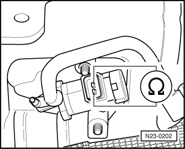
| Test the change-over valve for intake manifold flap. |
| –
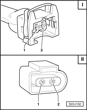
| Disconnect plug from change-over valve for intake manifold flap -N239 -. |
|
|
|