
Octavia Mk1
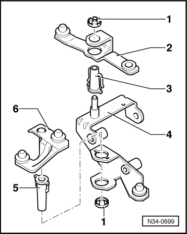
| Summary of components - reverse-shift mechanism at the gearbox |
 Note
Note| Grease bearing and friction surfaces with grease -G 000 450 02-. |

| 1 - | 20 Nm |
| q | self-locking |
| q | always replace → Electronic Catalogue of Original Parts |
| q | Shift lever on gearbox |
| 2 - | Gearbox shift lever |
| q | only fits in one position on the gearshift shaft |
| 3 - | Gasket ring |
| 4 - | Selector rod |
| 5 - | Shift rod - front |
| 6 - | Console |
| q | with relay lever and intermediate lever |
| q | Removal and installation of relay lever and intermediate lever → Fig. |
| q | Modification as of 08.98 new console → Fig. |
| q | Installation of the new console on the gearbox up to 07.98 → Fig. |
| 7 - | Coupling rod |
| 8 - | Shift rod with balancing weight |
| 9 - | Shield |
| q | is fitted on the selector lever |
| 10 - | Screw |
| q | for warm-type clamp Pos. 11 to shift rod Pos. 13 |
| 11 - | Open warm-type clamp |
| 12 - | Plug |
| 13 - | Gear shift rod |
| 14 - | Collar nut, 20 Nm |
| q | self-locking |
| q | for warm-type clamp Pos. 11 to shift rod Pos. 13 |
| 15 - | Selector lever |
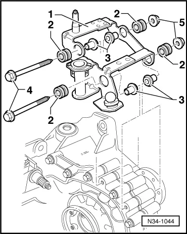
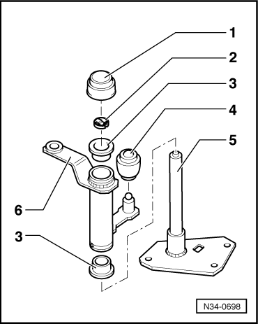
| 16 - | Bracket |
| q | with guide shaft |
| q | Removal and installation of the guide shaft → Fig. |
| 17 - | Shield |
| 18 - | 25 Nm |
| 19 - | 25 Nm |
| q | Console to gearbox |
| 20 - | Gearbox |
|
|
|
|
|
|