
Octavia Mk1
|
 Note
Note| This is the only adjusting work when installing an exchange component → Chapter. |
| – | Install components for adjusting the clutch clearance without adjusting washer Pos. 4 and reverse gear-clutch Pos. 5. |
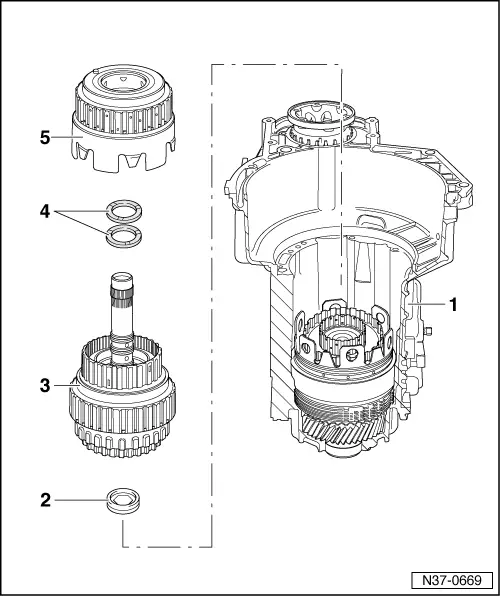
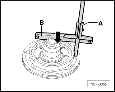
| 1 - | Gearbox housing |
| q | Planetary gear fitted up to small drive shaft → Anchor |
| 2 - | Axial needle bearing with washer |
| q | Axial needle bearing points to the small drive shaft |
| q | Washer points to -K3- |
| 3 - | 1st up to 3rd gear - clutch -K1- with 3rd and 4th gear - clutch -K3- with turbine shaft |
| q | on certain gearboxes, the clutches -K1- and -K3- can be pressed together as shown here |
| q | there are two different versions of turbine shafts, depending on the installed converter → Chapter |
| 4 - | Shims |
| q | do not install to adjust the clutch clearance |
| q | up to 3 adjusting washers can be installed |
| q | washers are available in different colours depending on the thickness |
| 5 - | Reverse gear - clutch -K2- |
| q | must not be installed necessarily for determining the adjusting washer(s) |
| q | install for control measurement |
|
|
|
|
|
|
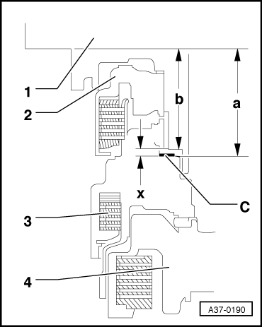
| Measured value 1 | = | 88.5 mm |
| - Measured value 2 | = | - 34.3 mm |
| determined value “a” | = | 54.2 mm |
|
|
|
| measured value | = | 70.5 mm |
| - Straightedge | = | - 19.5 mm |
| determined value “b” | = | 51.0 mm |
|