
Octavia Mk1
 Note
Note| t | Before pressing on the inner ring/tapered-roller bearing heat up to 100°C. |
| t | Adjusting ring for tapered roller bearing - before pressing in outer ring/tapered roller bearing - heat up to 100°C. |

| 1 - | Differential gear housing |
| q | with riveted pinion for final drive |
| q | The pinion for the final drive is riveted on the differential gear housing and subsequently machined |
| q | if the differential gear housing or the pinion for the final drive is damaged, the differential gear housing is replaced together with the riveted pinion for the final drive |
| q | Number of teeth of the final drive pinion → Chapter |
| q | there are various differential gear housings depending on the diameters of the tapered-roller bearings. |
| 2 - | Output shaft for joint flange |
| q | removing and installing → Chapter |
| 3 - | Inner ring/tapered-roller bearing |
| q | there are different sizes of tapered-roller bearings. The fitting position can vary |
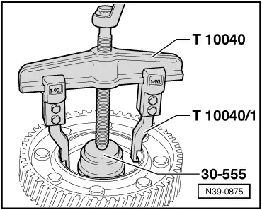
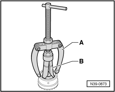
| q | remove the two “identical” bearings on both sides → Fig. |
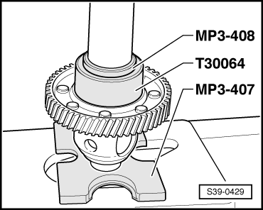
| q | remove the “larger” bearing → Fig. |
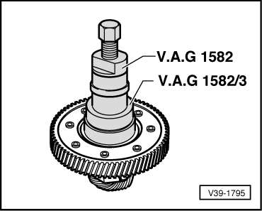
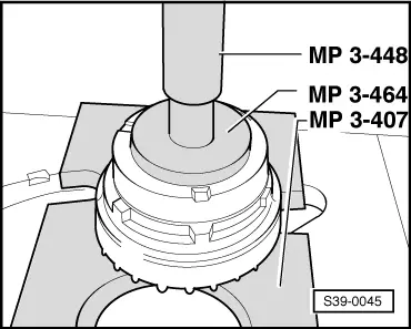
| q | press on → Fig. (for bearings of equal size on both sides) |
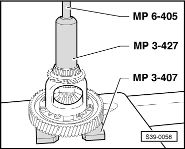
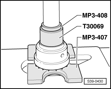
| q | press into the housing for the “larger” bearing on one side → Fig. |
| 4 - | Outer ring/tapered-roller bearing |
| q | only remove and install if the bearing body is heated Pos. 5 |
| q | drive out with drift |
| q | installing → Fig. |
| 5 - | Bearing body for tapered-roller bearing |
| q | there are various bearing bodies |
| q | removing and installing → Chapter |
| q | Remove inner rings for tapered-roller bearing → Fig. |
| q | Press in outer ring for tapered-roller bearing → Fig. |
| q | Press on inner ring for tapered-roller bearing → Fig. |
| 6 - | O-ring |
| q | always replace → Electronic Catalogue of Original Parts |
| 7 - | O-ring |
| q | always replace → Electronic Catalogue of Original Parts |
| 8 - | Adjusting ring for tapered roller bearing |
| q | removing and installing → Chapter |
| 9 - | Output shaft for joint flange |
| q | removing and installing → Chapter |
| 10 - | Outer ring/tapered-roller bearing |
| q | only remove and install if the adjusting ring is heated Pos. 8 |
| q | pull out → Fig., if necessary drive out with drift |
| q | installing → Fig. |
| 11 - | Inner ring/tapered-roller bearing |
| q | there are different sizes of bearings |
| q | before detaching, remove Pos. 12 and 13 |
| q | detach → Fig. (for bearings of equal size on both sides) |
| q | pressing on → Fig. |
| 12 - | Tappet bushing |
| q | remove together with drive wheel for speedometer Pos. 13 |
| q | remove with a drift |
| 13 - | Drive wheel for speedometer |
| q | drive out with drift |
| q | position with tappet bushing Pos. 12 |
| 14 - | Stop disc compound |
| q | position in the differential gear housing before inserting the differential bevel gears |
| 15 - | Differential bevel gear, small |
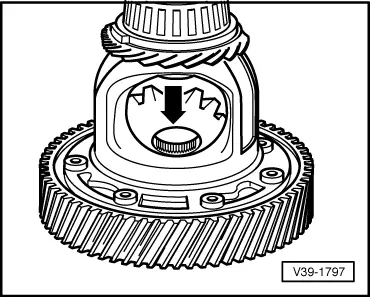
| q | inserting → Fig. |
| 16 - | Differential bevel gear, large |
| q | inserting → Fig. |
| 17 - | Circlip |
| q | remove circlip only after removing the joint flange, as the pressure spring is pretensioned |
| q | removing → Fig. |
| 18 - | Differential bevel gear shaft |
| q | for removing, remove tensioning sleeve Pos. 19 |
| q | drive out with drift |
| q | when driving in, do not damage stop disc compound |
| 19 - | Tensioning sleeve |
| q | replace |
| q | to secure the differential bevel gear shaft |
| q | removing and installing → Fig. |
|
|
Note
|
|
|
|
|
|
|
|
|
|
|
|
|
|
|
|
|
|
|
|