skoda Workshop Repair Guides

Skoda Workshop Service and Repair Manuals

Overview of selectable functions > < Perform self-diagnosis
Connecting vehicle system tester V.A.G 1552 and selecting functions
Connecting vehicle system tester -V.A.G 1552- and selecting functions
  Note
t  The description which follows relates to the vehicle system tester -V.A.G 1552- using program card 5.0 or higher version.
t  The use of vehicle diagnosis, measurement and information system -VAS 5051- and the fault read-out scan tool -V.A.G 1551 - with integrated printer is similar. A minor deviation on the display read-out is possible.
Test requirements
l  Selector lever in position “P” and hand brake applied.
l  Supply voltage of the vehicle OK
l  Fuses OK → Current flow diagrams and Fitting locations.
l  Earth connection and earth point for gearbox OK → Current flow diagrams and Fitting locations.
–  Check battery earth strap and earth strap between battery and gearbox.
   
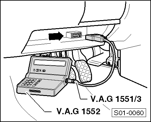
–  Connect vehicle system tester -V.A.G 1552- when the ignition is switched off with diagnostic cable -V.A.G 1551/3 - to the diagnostic connector -arrow-.
  Note
The diagnostic connection is located in the storage area below the steering column.
–  Switch on ignition.
  S01-0060
Readout on display:
  Note
t  Additional operating instructions can be interrogated via the HELP button of the -V.A.G 1552-.
t  The button is used for moving forward in the program.
t  If this display does not appear: → V.A.G 1552; vehicle system tester; operating instructions
–  Enter address word 02 “Gearbox electronics” and confirm with Q.
 
Vehicle system test               HELP
Enter address word XX
Readout on display:
Control unit identification
Example:
t  01M 927 733 AG1)
t  AG4 gearbox 01M: Automatic 4 speed gearbox 01M
t  2770: EPROM (program status)
t  Coding 00000: Not needed at present.
t  WSC XXXXX ⇒ Operating instructions -V.A.G 1552-
1) Assignment of the control unit → Electronic Catalogue of Original Parts
 
01M927733AG  AG4 gearbox 01M  2770   ->
Coding 00000                   WSC XXXXX
Readout on display:
–  By pressing the HELP button a list of possible fault causes is displayed.
–  After removing the possible fault causes re-enter address word 02 for “Gearbox electronics” and confirm.
If “The control unit does not respond!” is displayed again:
 
The control unit does not respond!        HELP
Readout on display:
–  Check supply voltage of the control unit:
–  Perform test step 1 → Chapter.
–  Check wiring to diagnostic connection → Current flow diagrams and Fitting locations.
–  → Chapter, Fault table, fault table 65535 control unit defective!
–  Press key.
 
The control unit does not respond!        HELP
Readout on display:
 
Vehicle system test               HELP
Select function XX

Overview of selectable functions > < Perform self-diagnosis