| Electric/electronic components and fitting locations |
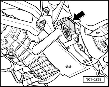
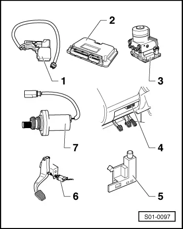
| 1 - | Four-wheel drive control unit -J492- |
| –
| forms a single unit with the oil pressure control motor -V184 - and the hydraulic temperature sender -G271- |
| –
| is checked by self-diagnosis as of 10.99 → Chapter |
| –
| the following signals are transmitted to the four-wheel drive control unit via the data BUS -J492-: |
| –
| Accelerator pedal position |
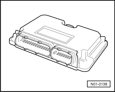
| 3 - | ABS control unit -J104- |
| –
| Fitting location: at the hydraulic unit in left of engine compartment |
| –
| the following signals are transmitted to the four-wheel drive control unit via the data BUS -J492-: |
| –
| Longitudinal acceleration |
| 4 - | Diagnostic connection |
| –
| Fitting location: in the storage compartment on the driver's side |
| 5 - | Handbrake warning switch -F9- |
| –
| can be checked in the measured value block, display group number 001 → Chapter and in the electrical test → Chapter |
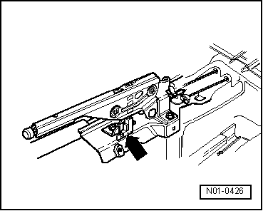
| 6 - | Brake light switch -F- |
| –
| Fitting location: at brake pedal |
| –
| can be checked in the measured value block, display group number 001 → Chapter and in the electrical test → Chapter |
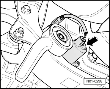
| 7 - | Pump for Haldex coupling -V181- |
| –
| can be checked in the actuator diagnosis → Chapter and in the electrical test → Chapter. |
|
|
|