Octavia Mk1
| Summary of components - removing and installing control cables |
 Note
Note| Grease all bearing and contact surfaces with Polycarbamide Grease -G 052 142 A2-. |

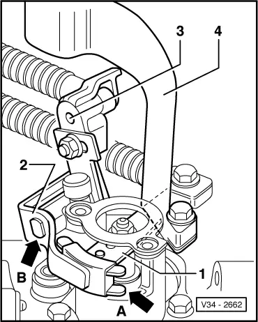
| 1 - | Shift cable |
| q | Fitting position → Chapter |
| 2 - | Selector cable |
| q | detach from driver Pos. 18, to do so pull the peg in -direction of arrow- |
| q | Fitting position → Chapter |
| q | fit on before installing shift cable |
| 3 - | Lock washer |
| q | do not damage bellows when removing |
| 4 - | 25 Nm |
| q | with shank |
| q | Shift cable at gearbox shift lever |
| 5 - | Insulated piece |
| q | for shift cable/gearbox shift lever |
| q | for replacing the bellows, push out of the end piece |
| 6 - | Washer |
| q | insert between shift cable and gearbox shift lever |
| 7 - | Gearbox shift lever |
| q | insert in such a way that the interrupted spacing of the teeth matches the gearshift shaft |
| q | Fitting position → Fig. |
| q | after installing set shift mechanism → Chapter |
| 8 - | Square nut |
| q | self-locking |
| q | always replace → Electronic Catalogue of Original Parts |
| q | insert into gearbox shift lever |
| 9 - | 20 Nm |
| q | self-locking |
| q | always replace → Electronic Catalogue of Original Parts |
| q | for gearbox shift lever to gearshift shaft |
| 10 - | Bellows |
| q | carefully pull over shift cable/end part |
| q | Use grease for plug serration of clutch disc -G 000 100- |
| 11 - | 25 Nm |
| q | for cable support |
| 12 - | Cable support |
| 13 - | Spacer |
| 14 - | Grommet |
| q | for mounting of cable support to gearbox |
| 15 - | Bellows |
| q | carefully pull over selector cable/end part |
| q | Use grease for plug serration of clutch disc -G 000 100- |
| 16 - | Reversing lever |
| q | take off before removing the clutch control |
| q | Fitting position → Fig. |
| q | repairing → Chapter |
| 17 - | 15 Nm |
| q | self-locking |
| q | for relay lever/driver |
| q | release only for setting the shift mechanism |
| 18 - | Driver |
| q | with shaft for relay lever bearing |
| q | Fitting position → Fig. |
| q | repairing → Chapter |
| 19 - | Insulated piece |
| q | for selector cable/driver |
| q | use drift to press in and press out |
| 20 - | 25 Nm |
| q | for balancing weight |
| 21 - | Balancing weight |
| q | remove for setting the gearshift mechanism |
| 22 - | 15 Nm |
| q | self-locking |
| q | for control cables to shift housing |
| 23 - | Rubber washer |
| 24 - | Insulated piece |
| q | for shift cable to shift lever |
| q | use drift to press in and press out |
| 25 - | Insulated piece |
| q | for selector cable to selector angle plate |
| q | use drift to press in and press out |