
Octavia Mk1
|
|
|
|
|
|

|
|
|
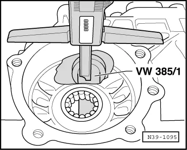
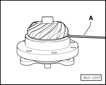
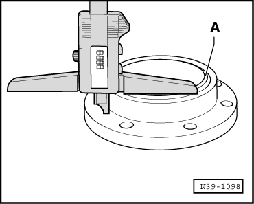
| on the digital depth gauge read off value | 72.50 mm |
| half of Ø the universal measuring rod -VW 385/1- | + 16.00 mm |
| Dimension -A- | = 88.50 mm |
|
|
 Note
Note
|
|
|
|
|
|
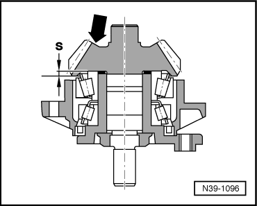
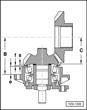
| recorded stage dimension -s- | 3.95 mm |
| Clearance -f- determined with feeler gauge | + 0.93 mm |
| Value -e- determined with depth gauge | + 20.12 mm |
| Setting dimension -C- with shank bevel gear deviation “D” (C + D) | + 65.60 mm |
| Dimension -B- | = 90.60 mm |
|
|
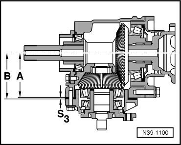
| Dimension -B- | 90.60 mm |
| Dimension -A- | - 88.50 mm |
| Thickness of adjusting washer S3 | = 2.10 mm |
Note
|
| Adjusting washer thickness (mm) | |||
| 1,20 | 1,50 | 1,80 | 2,10 |
| 1,25 | 1,55 | 1,85 | 2,15 |
| 1,30 | 1,60 | 1,90 | 2,20 |
| 1,35 | 1,65 | 1,95 | |
| 1,40 | 1,70 | 2,00 | |
| 1,45 | 1,75 | 2,05 | |
|