skoda Workshop Repair Guides

Skoda Workshop Service and Repair Manuals

Installing - engines with identification characters AEH, AKL > < Removing and installing the cylinder head - engines with identification characters AEH, AKL
Removing - engines with identification characters AEH, AKL
  Note
All cable straps which are detached or cut open when removing, should be fitted on again in the same place when installing.
Special tools and workshop equipment required
t  
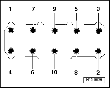
Wrench for cylinder head bolts, e.g. 3452
t  Extractor -T10112-
t  Socket insert -T10070-
t  Catch pan, e.g. -VAS 6208-
t  
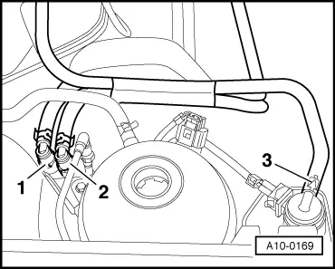
Pliers for spring strap clamps
Engine installed
–  On models fitted with a coded radio set, pay attention to the coding; determine if necessary.
–  Disconnect the earth strap from the battery with the ignition off.
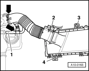
–  Remove top part of intake manifold → Chapter.
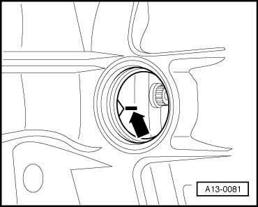
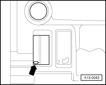
–  Open the cap of the coolant expansion reservoir.
–  Drain coolant → Chapter.
–  Unscrew pre-exhaust pipe from exhaust manifold → Chapter.
   
–  Detach air guide hose at throttle valve connection and at vent housing of the crankcase ventilation -arrows-.
–  Detach vent hose -1- and unplug connector for air mass meter -2-.
–  Unscrew bolts -3- and -4- and remove air filter housing.
  A10-0163
–  Rotate crankshaft to TDC for cylinder 1 -arrow- (vehicles with manual gearbox). TDC marking on flywheel and reference mark must be aligned.
Marking on flywheel and reference mark must be aligned.
  A13-0081
–  Rotate crankshaft to TDC for cylinder 1 -arrow- (vehicles with automatic gearbox). TDC marking on drive plate and reference mark must be aligned.
TDC marking on drive plate and reference mark must be aligned.
  Note
  A13-0043
When engine removed, position vibration damper to TDC for cylinder 1 -arrows-.
–  Remove top toothed belt guard.
–  Slacken tensioning pulley and take timing belt off camshaft sprocket.
  WARNING
The fuel system is under pressure! Before opening the system lay cleaning cloths around the connection point. Reduce pressure by carefully releasing the connection point.
  A13-0076
–  Detach fuel feed line -1- and fuel return-flow line -2- by pressing on the release buttons. Lines and line connections are colour-coded.
–  Detach hose -3- at the ACF tank.
–  Disconnect plug at phase sensor (Hall sender -G40-) and at all four injection valves.
–  Detach cable harness for the fixtures and run out to the side.
–  Use the extractor -T10112- to unplug spark plug connector and place to the side → Chapter.
–  Unscrew M8 bolts for rear toothed belt guard.
–  Detach left coolant hose at cylinder head.
–  Unscrew left coolant connection fitting at cylinder head.
–  Pull out coolant pipe towards the left.
–  Remove cylinder head cover → Chapter.
  A10-0169
–  Release the cylinder head bolts in the order -1 to 10-.
–  Remove cylinder head with cylinder head gasket.
  N15-0026

Installing - engines with identification characters AEH, AKL > < Removing and installing the cylinder head - engines with identification characters AEH, AKL