
Octavia Mk1
| Summary of components - engines with identification characters AVU, BFQ |
 Note
Note| t | Cylinder head and ladder frame must always be replaced together. |
| t | After carrying out work on the valve gear, carefully crank engine at least 2 revolutions to ensure that no valve touches the piston when the engine is started. |
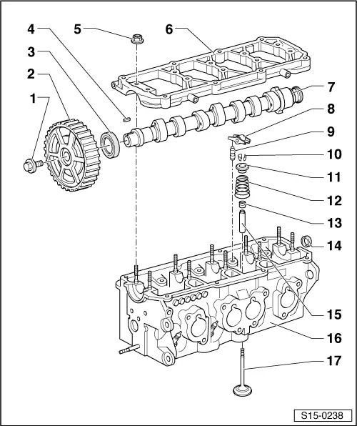
| 1 - | 100 Nm |
| q | to release and tighten use counterholder -T30004 (3415)- |
| 2 - | Camshaft sprocket |
| q | for removing and installing, remove toothed belt → Chapter |
| q | Installation position fixed by woodruff key -pos. 4- |
| q | for engines with identification characters AVU with rotor for camshaft position sensor -G163- |
| 3 - | Sealing ring |
| q | Do not oil sealing lip of gasket ring |
| q | replace → Chapter |
| 4 - | Woodruff key |
| 5 - | 20 Nm |
| 6 - | Ladder frame |
| q | with integrated camshaft bearings |
| q | Bearing 1 on camshaft sprocket |
| q | Observe the tightening sequence of the camshaft bearings → Chapter |
| q | Apply sealant -D 188 800 A1- carefully in the sealant groove and to the bottom sealing surface |
| q | reworking of the sealing surface opposite the cylinder head is not permitted |
| 7 - | Camshaft |
| q | for engines with identification characters AVU without rotor for camshaft position sensor -G163- |
| q | removing and installing → Chapter |
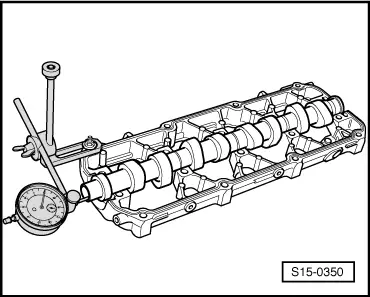
| q | Inspecting axial play → Fig. |
| q | Slack: max. 0.01 mm |
| 8 - | Roller rocker arm |
| q | do not interchange |
| q | inspect roller bearings |
| q | oil contact surface |
| q | when installing, fasten at supporting element with locking clip |
| 9 - | Supporting element |
| q | do not interchange |
| q | with hydraulic valve clearance compensation |
| q | oil contact surface |
| 10 - | Valve collets |
| 11 - | Valve spring retainer |
| 12 - | Valve spring |
| q | removing and installing: |
| – | with cylinder head removed, with valve lever -MP1-211 (VW 541/1a,/5)- and assembly device for valves -MP1-213 (2036)- with valve supporting plate -MP1-218- |
| – | (with cylinder head installed) → Chapter |
| 13 - | Valve stem seal |
| q | replace → Chapter |
| 14 - | Plug |
| q | for removal, only push the rubber through the middle using a screwdriver and release |
| q | fit on evenly and without tilting |
| 15 - | Valve guide |
| q | check → Chapter |
| 16 - | Cylinder head |
| q | pay attention to the notes → Anchor |
| q | reworking valve seats → Chapter |
| 17 - | Valve |
| q | do not rework, only grinding in is permissible |
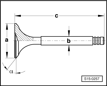
| q | Valve dimensions → Fig. |
Note
|
|
| Dimension | Inlet valve | Exhaust valve | |
| Ø a | mm | 39,5 ± 0,15 | 32,9 ± 0,15 |
| Ø b | mm | 5,98 ± 0,007 | 5,965 ± 0,007 |
| c | mm | 93,85 | 93,85 |
| α | ∠° | 45 | 45 |