skoda Workshop Repair Guides

Skoda Workshop Service and Repair Manuals

Reworking valve seats - engines with identification characters AVU, BFQ > < Inspecting valve guides - engines with identification characters AVU, BFQ
Reworking valve seats - engines with identification characters AEH, AKL
Special tools and workshop equipment required
t  Depth gauge/caliper gauge
t  
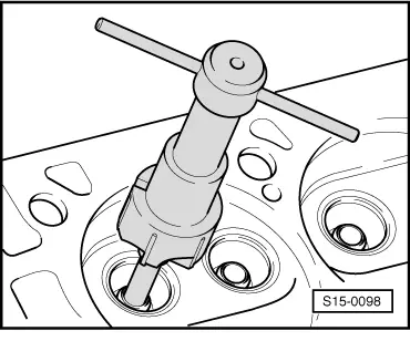
NAC milling cutter for reworking valve seats
t  Grinding paste
  Note
t  When carrying out repairs on engines with leaking valves, it is not sufficient to machine or replace the valve seats and valves. It is also necessary to inspect the valve guides for wear, particularly on engines with a high mileage.
t  
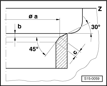
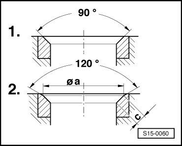
Rework valve seats only sufficiently in order to obtain a proper contact pattern. Calculate the maximum permissible reworking dimension before commencing. If the reworking dimension is exceeded, the proper operation of the hydraulic valve clearance compensation is no longer ensured. If this is the case replace the cylinder head.
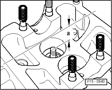
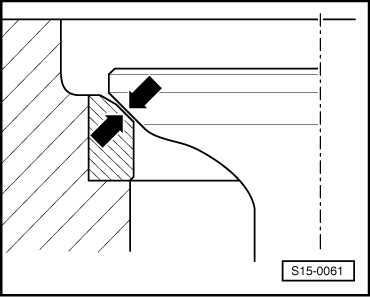
Calculating maximum permissible reworking dimension
–  Insert valve and press firmly against the valve seat.
  Note
If the valve is replaced when carrying out repair work, use a new valve for the measurement.
   
–  Measure distance -a- between the end of the valve stem and the upper face of the cylinder head.
–  Calculate max. permissible reworking dimension from the distance -a- measured and the minimum dimension.
Minimum dimension: inlet valve…33.8 mm
Outlet valve...34.1 mm
Distance measured -a- minus minimum dimension = max. permissible reworking dimension.
Example:
  V15-0640

-
distance measured -a-
Minimum dimension
34.5 mm
33.8 mm
=max. permissible reworking dimension0.7 mm

  Note
If the max. permissible reworking dimension is 0 mm, repeat measurement with a new valve. If the max. permissible reworking dimension is again 0 mm, replace cylinder head.
   
Reworking valve seats
  S15-0059
Dimension Valve seats
Ø ammValve seat diameter39.2 -0.1 - inlet valve
32.4 -0.1 - exhaust valve
bmmmax. permissible reworking dimension
cmmValve seat width1.9 up to 2.1 - inlet valve
2.3 up to 2.5 - exhaust valve
Z Bottom edge of cylinder head
45° Valve seat angle
30° Top correction angle

Work procedure
Reworking can be carried out with a machine or by hand. The following conditions must be met:
l  Wear limit of valve guides must not exceed the permissible dimension → Chapter.
l  Use NAC milling cutter with carbide metal tips (min. 90 HRC).
   
Reworking valve seats with NAC milling cutter
–  Place cylinder head on a felt base and secure to prevent it from turning.
–  Match diameter of guide drift to diameter of valve guide.
  S15-0098
Valve guideØ Guide drift mm
Inlet valve7,0 -0,01
Exhaust valve

–  Match diameter of milling cutter to diameter of valve seat.
   
Valve seatØ Milling cutter 90° mmØ Milling cutter 120° mm
Inlet valve4141
Exhaust valve3434

   
Milling sequence
 - 1. Mill valve seat with 90° milling cutter until a perfect contact pattern is achieved. (Do not exceed maximum permissible reworking dimension!)
 - 2. Initially mill top correction angle with 120° milling cutter until the valve seat diameter „a“ or valve seat width „c“ is achieved → Anchor.
  S15-0060
–  Grind in valve/valve seat with fine grinding paste so as to achieve a perfect contact pattern -arrows-.
–  Inspect valve for tightness.
The inspection can be carried out with water colour (perfect contact pattern over entire circumference) or by filling fuel into the combustion chamber (no fuel must flow out at the valve seat).
  Note
After installing the cylinder head, check the hydraulic bucket tappets → Chapter.
  S15-0061

Reworking valve seats - engines with identification characters AVU, BFQ > < Inspecting valve guides - engines with identification characters AVU, BFQ