skoda Workshop Repair Guides

Skoda Workshop Service and Repair Manuals

Checking outer joint on outside > < Removing and installing the outer CV joint
Removing and installing the inner CV joint
Removing
   
–  Drive off cover and joint boot with a drift.
–  Open warm-type clamp.
–  Push the cover with the warm-type clamp in direction of outer joint.
  A42-0289
–  Remove circlip with circlip pliers.
–  Press the inner joint off the drive shaft.
  S40-0409
Press off the inner joint
Install
–  Push the open warm-type clamp on the drive shaft.
–  Push the sheet metal cover with the joint boot onto the drive shaft.
–  Pay attention to the fitting position of the disc spring at the inner joint.
  S40-0232
Fitting position of the disc spring at inner joint
1 - Disc spring
  S40-0294
–  Thinly coat the serration -A- with joint grease.
–  Press the joint up to the stop.
  A42-10049
Press on the inner joint
  Note
Chamfer on inner diameter of the ball hub (serration) must point towards the bearing collar of the drive shaft.
–  Install circlip.
–  Fill the joint with allowed grease quantity → Chapter.
–  Clean and degrease the end faces of the joint.
–  Clean and degrease the end face of the sheet metal cover for the joint boot which rests against the joint.
  S40-0233
–  Apply sealant -D 454 300 A2- on the shaded surfaces of the cover.
t  Sealant bead: apply continuously, Ø 2...3 mm, in the area of the holes from inside -arrow-.
–  Push the sheet metal cover with the joint boot onto the joint.
  A42-0277
–  Align the cover with the joint boot to the screw holes with screws -arrows-.
  Note
The alignment must be performed very carefully as this is no longer possible after striking it.
–  Use a plastic hammer to strike the sheet metal cover with the joint boot on the joint.
–  Wipe off any excess sealant, if necessary.
–  Remove the protective foil from the gasket and stick the gasket into the joint from the gearbox side.
  A42-0292
–  Insert the joint boot into the outer groove of the shaft -arrow B-.
–  Install warm-type clamp.
  A40-10020
Tighten warm-type clamp
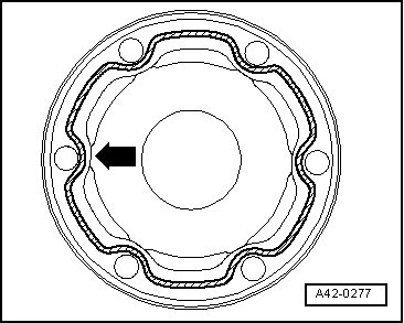
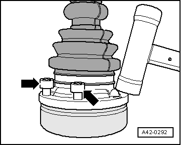
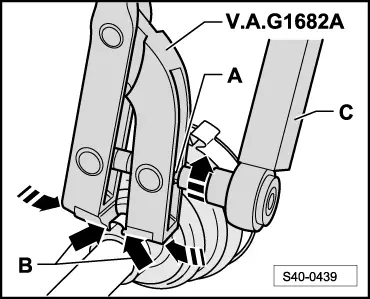
–  Position the tensioning pliers as shown in the figure. Make sure the cutting edges of the pliers are positioned in the corners -arrows B- of the open warm-type clamp.
–  Tighten the open warm-type clamp by turning the spindle with a torque wrench (do not tilt the pliers during this process.)
  Note
t  In view of the hard material (as opposed to rubber) of the joint boot, which requires the use of a stainless steel open warm-type clamp, the latter can only be tightened with tensioning pliers, e. g. -V.A.G 1682 A-.
t  Tightening torque: 25 Nm.
t  Use torque wrench -C-.
t  
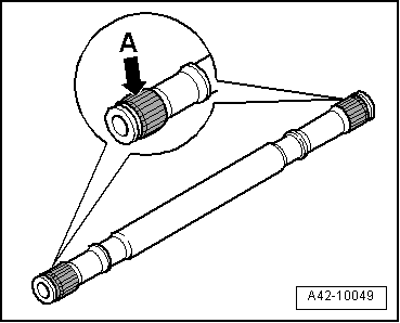
Ensure that the thread of the spindle -A- of the pliers is smooth. Lubricate if necessary with grease.
t  If it is not smooth, e.g. if the thread is dirty, the necessary clamping force of the open warm-type clamp is not reached at the given torque.
  S40-0439

Checking outer joint on outside > < Removing and installing the outer CV joint