skoda Workshop Repair Guides

Skoda Workshop Service and Repair Manuals

Setting the timing > < Change camshaft fixer/locator T10171 in camshaft fixer/locator T10171 A
Test timing
Test timing
Special tools and workshop equipment required
t  Adapter for dial gauge -T10170- or -T10170 A-
t  Camshaft fixer/locator -T10171 A-
Change camshaft fixer/locator -T10171- in camshaft fixer/locator -T10171 A- → Chapter.
t  Dial gauge, commercially available
Test sequence
–  Remove engine cover → Chapter.
   
–  Release screws -2- and remove retaining clip -1-.
–  Disconnect plug -3- from charge pressure sender -G31- with intake air temperature sender 2 -G299-.
–  Unhook the hoses at the pressure pipe and open the cable guide.
–  Press the retaining clips -arrows- towards the outside and pull the pressure pipe out towards the top.
–  Then pull off the pressure pipe from the exhaust turbocharger.
  A21-10169
–  Disconnect plug -arrow- at oil pressure switch -F1-.
  A17-10341
–  Release screw -1- for earth lead.
  A19-10615
–  Release screws -1- and -2- and push the left coolant pipes to the left side.
  A19-10616
–  Release screws -arrows-, take off cap -1- and -2-.
–  Remove ignition coil from cylinder 1 → Chapter and release the spark plug.
  A15-10531
–  Screw adapter for dial gauge -T10170 - up to the stop into the spark plug thread.
–  Insert the dial gauge -A- with extension -T10170/1- up to the stop and fix in place using the clamping screw -arrow-.
–  Rotate the crankshaft in direction of rotation of engine on TDC for cylinder 1. Note down the position of the small pointer of the dial gauge.
  S15-0279
The holes -arrows- in the camshafts must be positioned as shown. If necessary rotate the crankshaft a further revolution (360°).
  Note
t  If the crankshaft was turned more than 0.01 mm past the top dead centre, the crankshaft must once again be turned approx 45° in the opposite direction of rotation of the engine. Then position the crankshaft in direction of rotation of engine on top dead centre of cylinder 1.
t  Permissible deviation from TDC of cylinder 1: ± 0.01 mm.
  S15-0280
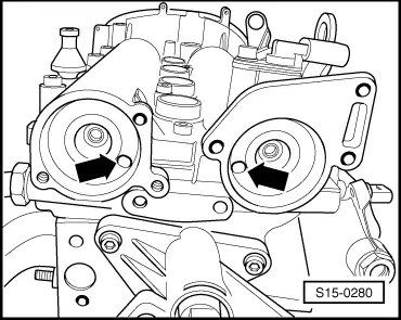
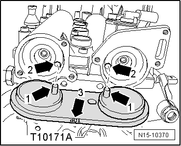
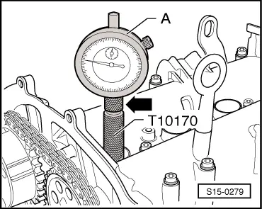
–  Insert camshaft fixer/locator -T10171 A - up to the stop into the holes in the camshaft housing.
l  
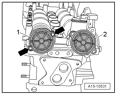
The locking bolts -arrows 1- must engage in the holes -arrows 2-. The inscription “TOP”-arrow 3- must be legible from above.
If the camshaft fixer/locator -T10171 A- is not insertable up to the stop in the camshaft openings, the timing is not correct and must be set → Chapter.
The timing is O.K., if the camshaft fixer/locator -T10171 A- can be inserted up to the stop into the camshaft openings.
Further installation occurs in a similar way in reverse order to removal. Pay attention to the following:
t  Replace the gasket rings for the caps of the camshafts and oil before assembly.
  N15-10370

Setting the timing > < Change camshaft fixer/locator T10171 in camshaft fixer/locator T10171 A