
Octavia Mk2
| Catalytic converter and component parts - Summary of components |
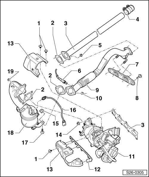
| 1 - | 8 Nm |
| q | first of all screw in all fixing screws by hand when installing |
| 2 - | Gasket |
| q | replace |
| 3 - | Intermediate pipe |
| 4 - | Clamping sleeve, 23 Nm |
| q | Tighten bolted connections evenly |
| 5 - | 23 Nm |
| q | replace |
| q | Coat stud bolts of exhaust pipe with hot bolt paste -G 052 112 A3- |
| 6 - | Lambda probe downstream of catalytic converter -G130-, 50 Nm |
| q | the thread of new lambda probes must be coated with assembly paste |
| q | for re-used lambda probe, only coat the thread with hot bolt paste -G 052 112 A3-; the paste must not get into the slots of the probe body |
| 7 - | Hanger |
| 8 - | 23 Nm |
| 9 - | Exhaust pipe |
| q | with decoupling element |
| q | do not twist decoupling element more than 10° - risk of damage |
| 10 - | 23 Nm |
| q | replace |
| 11 - | Exhaust gas turbocharger |
| q | The exhaust gas turbocharger and the exhaust manifold can only be replaced together |
| 12 - | Support |
| 13 - | Heat shield |
| 14 - | 16 Nm |
| q | replace |
| q | Coat stud bolts of exhaust manifold with hot bolt paste -G 052 112 A3- |
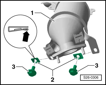
| 15 - | Reinforcement clip |
| q | Assembly → Fig. |
| 16 - | Lambda probe -G39-, 50 Nm |
| q | the thread of new lambda probes must be coated with assembly paste |
| q | for re-used lambda probe, only coat the thread with hot bolt paste -G 052 112 A3-; the paste must not get into the slots of the probe body |
| 17 - | 23 Nm |
 Caution
|
| 18 - | Catalytic converter with exhaust pipe |
| q | removing and installing → Chapter |
| 19 - | 23 Nm |
| q | replace |
| q | Coat stud bolts of exhaust gas turbocharger with hot bolt paste -G 052 112 A3- |
|
|