
Octavia Mk2
| Fitting location of the injection system |
| Right engine compartment side |

| 1 - | Control valve for fuel pressure -N276- |
| 2 - | High pressure pump with fuel pressure regulating valve -N276- |
| q | removing and installing → Chapter |
| 3 - | Solenoid valve 1 for activated charcoal filter -N80- |
| 4 - | Intake air temperature sender -G42- and intake manifold pressure sender -G71- |
| 5 - | Engine control unit -J623- |
| q | removing and installing → Chapter |
| 6 - | Knock sensor 1 -G61- |
| q | at rear cylinder block |
| q | 20 Nm |
| 7 - | Engine speed sender -G28- |
| q | removing and installing → Chapter |
| 8 - | lambda probe -G39- and heating for lambda probe -Z19- |
| 9 - | Lambda probe downstream of catalytic converter -G130- and heater of lambda probe 1 downstream of catalytic converter -Z29- |
| 10 - | Camshaft adjustment valve 1 -N205- |
| 11 - | Ignition coils with a power output stage |
| q | removing and installing → Chapter |
| Left engine compartment side |

| 1 - | Hall sender -G40- |
| 2 - | Throttle valve control unit -J338- |
| q | removing and installing → Chapter |
| q | clean → Chapter |
| q | in case of replacement, erase initialisation values and adapt the engine control unit -J623- → Vehicle diagnosis, testing and information system VAS 5051. |
| 3 - | Fuel pressure sender -G247- |
| q | check → Chapter |
| 4 - | Charge pressure sender -G31- with intake air temperature sender 2 -G299- |
| 5 - | Clutch position sender -G476- |
| 6 - | Coolant temperature sender at radiator outlet -G83- |
| 7 - | Coolant temperature sender -G62- |
| 8 - | electrical plug connections of the lambda probes |
| 9 - | Oil pressure switch -F1- |
| q | in the left cylinder head |
| q | check → Chapter |
| 10 - | Solenoid valve for charge pressure control -N75- |
| q | screwed onto the exhaust turbocharger |
| 11 - | Turbocharger divert air valve -N249- |
| Engine - suction side |
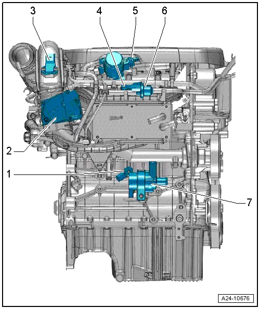
| 1 - | Knock sensor 1 -G61- |
| q | Summary of components → Chapter |
| 2 - | Throttle valve control unit -J338- |
| q | removing and installing → Chapter |
| q | clean → Chapter |
| q | in case of replacement, erase initialisation values and adapt the engine control unit -J623- → Vehicle diagnosis, testing and information system VAS 5051. |
| 3 - | Charge pressure sender -G31- with intake air temperature sender 2 -G299- |
| 4 - | Intake air temperature sender -G42- and intake manifold pressure sender -G71- |
| 5 - | Control valve for fuel pressure -N276- |
| 6 - | Solenoid valve 1 for activated charcoal filter -N80- |
| 7 - | Coolant recirculation pump -V50- |
| q | removing and installing → Chapter |
| Engine - gearbox side |
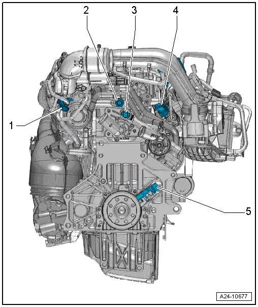
| 1 - | Solenoid valve for charge pressure control -N75 - |
| q | screwed onto the exhaust turbocharger |
| 2 - | Oil pressure switch -F1- |
| q | check → Chapter |
| 3 - | Coolant temperature sender -G62- |
| 4 - | Fuel pressure sender -G247- |
| q | check → Chapter |
| 5 - | Engine speed sender -G28- |
| q | Summary of components → Chapter |
| q | removing and installing → Chapter |