skoda Workshop Repair Guides

Skoda Workshop Service and Repair Manuals

Inspect valve guides > < Reworking valve seats
Calculating maximum permissible reworking dimension
–  Insert valve and press firmly against the valve seat.
  Note
If the valve is replaced when carrying out repair work, use a new valve for the measurement.
   
–  Measure distance between the valve stem end and the upper face of the cylinder head.
–  Calculate max. permissible reworking dimension from the distance measured and the minimum dimension.
  S15-0293
Minimum dimension: inlet valve7.6 mm
Minimum dimension: outlet valve7.6 mm

“Measured distance” - “minimum dimension” = “max. permissible reworking dimension”.
Example:
   
Measured distance8.0 mm
- Minimum dimension7.6 mm
= max. permissible reworking dimension → Note0.4 mm

1)  The max. permissible reworking dimension is shown in the figures for reworking the valve seats as dimension “b”.
   
Reworking inlet valve seat
a = Ø 28.7 mm
b = max. permissible reworking dimension
c = 1.5...1.8 mm
Z = Bottom edge of cylinder head
α = 45° valve seat angle
β = 30° top correction angle
γ = 60° bottom correction angle
  S15-0217
Reworking exhaust valve seat
a = Ø 25.0 mm
b = max. permissible reworking dimension
c = approx. 1.8 mm
Z = Bottom edge of cylinder head
α = 45° valve seat angle
β = 30° top correction angle
γ = 60° bottom correction angle
Procedure
Reworking can be carried out by hand while complying with the following conditions:
l  Wear limit of valve guides must not exceed the permissible dimension.
l  Use NAC milling cutter with carbide metal tips (min. 90 HRC).
l  Press on the milling cutter using slight pressure and mill in such a way that an even removal of swarfs is ensured over the whole working surface.
  S15-0217
Reworking valve seats with NAC milling cutter
–  Place cylinder head on a felt base and secure to prevent it from turning.
–  Match diameter of guide drift to diameter of valve guide.
  S15-0098
Valve guideØ Guide drift in mm
Inlet valve6,0 -0,01
Exhaust valve

–  Match diameter of milling cutter to diameter of valve seat.
   
Valve seatØ Milling cutter 90°
mm
Ø Milling cutter 120°
mm
Ø Milling cutter 60°
mm
Inlet valve323221/34
Exhaust valve303021/34

   
Milling sequence
1 - Mill valve seat with 90° milling tool until until a perfect contact pattern is achieved. (Do not exceed maximum permissible reworking dimension!)
2 - Chamfer top correction angle with 120° milling cutter until valve seat diameter -a- is achieved → Anchor.
3 - Mill bottom correction angle with 60° milling cutter until valve seat width -c- is achieved → Anchor.
  S15-0062
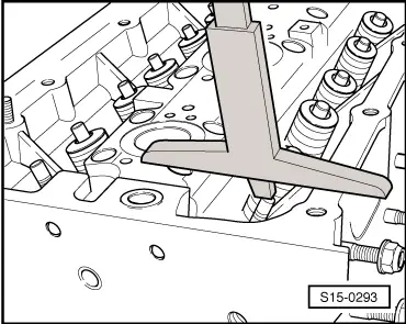
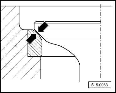
–  Grind in valve/valve seat -arrows- with fine grinding paste so as to achieve a perfect contact pattern.
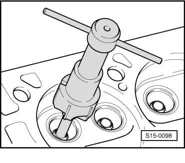
–  Check contact pattern e.g. with water colour (perfect contact pattern over entire circumference).
–  Install valve springs.
–  Check valves for tightness.
The tightness of the valves can be checked by filling petrol into the inlet and outlet canal (no petrol must flow out at the valve seat)
After completing the repair measure once again the distances between the valve stem ends and the upper face of the cylinder head and calculate the maximum permissible reworking dimension.
  Note
If the maximum permissible reworking dimension is exceeded, proper operation of the valve gear is no longer assured and the cylinder head must be replaced.
  S15-0063

Inspect valve guides > < Reworking valve seats