
Octavia Mk2
| Summary of components |
| The oil pressure switch -F1- is located in the front left of the cylinder head; removing and installing → Chapter. |
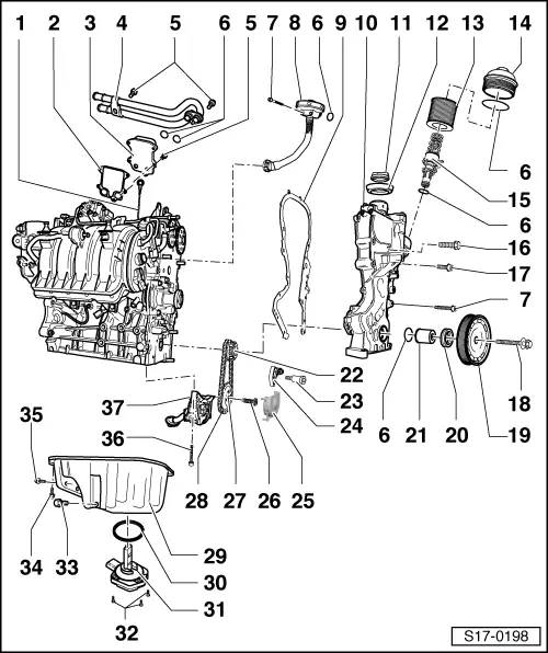
| 1 - | Dipstick |
| q | oil level must not exceed max. marking! |
| 2 - | Gasket |
| q | replace |
| 3 - | Oil cooler |
| 4 - | Coolant pipes |
| q | for oil cooler |
| 5 - | 8 Nm |
| 6 - | O-ring |
| q | replace |
| 7 - | 10 Nm |
| 8 - | Pressure control valve (PCV valve) |
| q | with ventilation hose |
| 9 - | Gasket |
| q | replace |
| 10 - | Timing case |
| q | removing and installing → Chapter |
| 11 - | Screw cap |
| q | Replace seal if damaged |
| 12 - | Gasket ring |
| q | replace if damaged |
| 13 - | Filter insert |
| 14 - | Oil filter cover, 25 Nm |
| 15 - | Valve |
| q | with short circuit valve |
| Opening pressure: 0.25 MPa (2.5 bar) excess pressure |
| q | with return-flow check valve |
| 16 - | 50 Nm |
| 17 - | 10 Nm |
| q | M6x22 mm |
| 18 - | Fixing screw |
| q | for crankshaft - belt pulley |
| q | replace |
| q | The clamping surface of the fixing screw must be free of grease and oil. |
| q | insert oiled (thread) |
| q | tighten → Chapter |
| 19 - | Crankshaft-belt pulley |
| q | The clamping surfaces of the crankshaft belt pulley must be free of grease and oil. |
| q | Removing and installing ribbed V-belt → Chapter |
| 20 - | Gasket ring for crankshaft in timing case |
| q | replace → Chapter |
| 21 - | Bushing |
| q | replace with repair set → Chapter |
| q | The clamping surfaces of the bushing must be free of grease and oil. |
| 22 - | Sprocket |
| q | for oil pump drive |
| q | removing and installing → Chapter |
| 23 - | 15 Nm |
| 24 - | Chain tensioner with tensioning rail and tensioning spring |
| q | for oil pump drive |
| q | Tightening torque: 15 Nm |
| q | only be replaced as a complete unit |
| 25 - | Cover |
| q | for chain sprocket of the oil pump |
| q | clipped into the oil pump housing |
| 26 - | 20 Nm + torque a further 90° (1/4 turn) |
| q | replace |
| 27 - | Sprocket |
| q | for oil pump |
| q | Counterhold sprocket with counterholder -T10172- |
| 28 - | Drive chain |
| q | for oil pump |
| q | mark running direction (installed position) before removing |
| q | removing and installing → Chapter |
| 29 - | Oil pan |
| q | removing and installing → Chapter |
| 30 - | Gasket ring |
| q | replace |
| q | oil before the assembly |
| 31 - | Oil level and oil temperature sender -G266 - |
| q | replace if damaged |
| q | check → Current flow diagrams and Fitting locations |
| 32 - | 10 Nm |
| 33 - | Oil drain plug, 30 Nm |
| q | with captive seal |
| q | replace |
| 34 - | 13 Nm |
| q | replace |
| q | Slacken and tighten the bolts at the gearbox side with socket insert - T10058- |
| 35 - | 40 Nm |
| 36 - | 25 Nm |
| 37 - | Oil pump |
| q | must be replaced completely |
| q | removing and installing → Chapter |