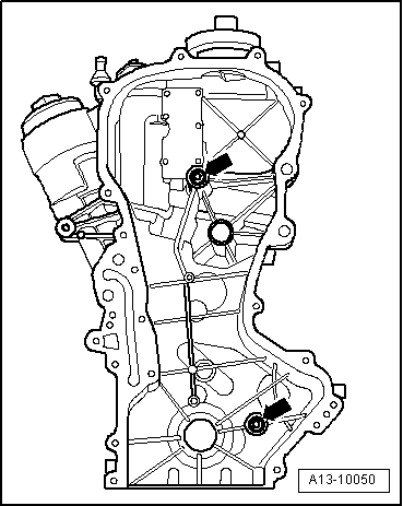
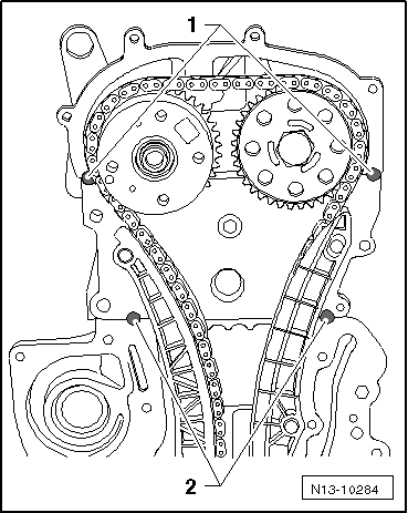
| Removing and installing the timing case |
| Special tools and workshop equipment required |
| t
| Supporting device -T30099- |
| t
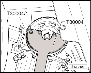
| Counterholder -T30004 (3415)- |
| t
| Bolt -T30004/1 (3415/1)- |
| t
| Hook for MP9-200 and T30099 -MP9-200/10 (10-222A/10) - |
| t
| Catch pan for workshop crane, e.g. -VAS 6208- |
| t
| Sealant remover gasket stripper (bearing code GST, bearing article no. R 34402), manufacturer Retech s.r.o. |
| t
| Cleaning agent and grease remover e.g. -D 000 401 04- |
| –
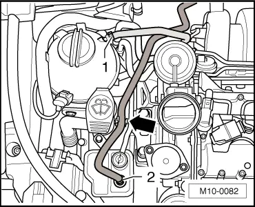
| Remove engine cover with air filter → Chapter. |
| –
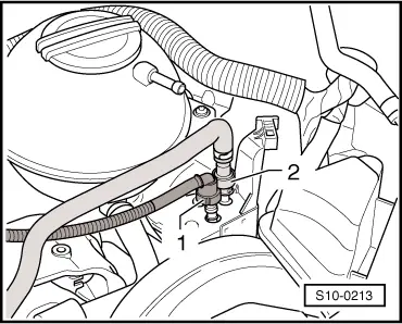
| Unscrew pressure control valve (PCV valve). |
|
|
|
 Caution
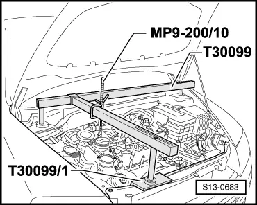
 Note
Note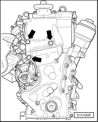
 WARNING