skoda Workshop Repair Guides

Skoda Workshop Service and Repair Manuals

Securing the engine to the assembly stand > < Removing and installing engine
Removing engine
Removing engine
Special tools and workshop equipment required
t  
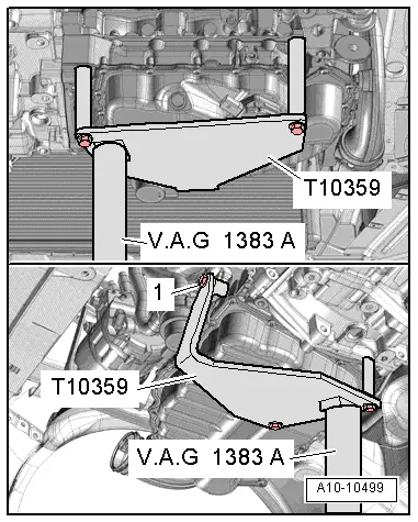
Engine/gearbox jack, e.g. -V.A.G 1383 A-
t  Double ladder, e. g. -VAS 5085-
t  Engine mount -T10359-
t  Removal tool for inner lining of the door panel -MP8-602/1 -
t  Pliers for spring strap clamps
t  Catch pan e.g. -VAS 6208 -
t  Grease -G 000 100-
t  Cable strap
  Note
t  The engine is removed downwards together with the gearbox.
t  All cable straps that have been loosened or cut open when the engine was removed must be fitted again in the same location when the engine is installed again.
t  Collect drained coolant in a clean container for reuse or proper disposal.
  Caution
When undertaking all installation work, particularly in the engine compartment because of its cramped construction, please observe the following:
t  
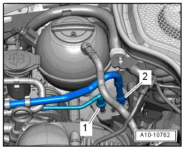
Lay lines of all kinds (e.g. for fuel, hydraulic fluid, the active charcoal container-unit, cooling fluid and refrigerant, brake fluid, vacuum) and electrical lines in such a way that the original line guide is re-established.
t  In order to avoid damage to the cables, ensure that there is adequate free access to all moving or hot components.
Observe all safety measures and notes for assembly work on the fuel, injection and ignition system and the charge air system as well as rules for cleanliness → Chapter.
–  Remove the air filter housing → Chapter.
   
–  Pull off ventilation tube -1- for crankcase ventilation.
–  Release screw -arrow-.
–  Remove intake manifold, to do slacken hose clamp -2-.
  Note
Seal inlet connection at turbocharger.
–  Before disconnecting the battery, if necessary remove the adapter for the anti-theft wheel bolts from the luggage compartment.
–  Remove battery and battery tray → Electrical System; Rep. Gr.27.
–  Remove the front right wheelhouse liner → Body Work; Rep. Gr.66.
Vehicles with front-wheel-drive
  N21-10192
–  Unbolt heat shield for right drive shaft -arrows-.
Continued for all vehicles
–  Remove right drive shaft → Chassis; Rep. Gr.40.
–  Unscrew the left drive shaft from the flange shaft of the gearbox and tie up as much as possible.
–  Remove pre-exhaust pipe → Chapter.
Vehicles with four-wheel drive
–  Remove propshaft → Gearbox; Rep. Gr.39.
Continued for all vehicles
–  Removing fan shroud → Chapter.
–  Drain coolant → Chapter.
–  Detach coolant hoses from radiator, heat exchanger and compensation bottle.
–  Disconnect the plug of the engine wiring harness from the engine control unit → Chapter.
  A10-1633
–  Release duct for engine wiring harness -arrow- and pull out upwards.
–  Expose the rear left engine wiring harness at the bulkhead plenum chamber.
  S10-0319
–  Open the bracket of the cable guide -arrows-.
  N10-0461
–  Expose the plug connection -1- and disconnect it.
–  Open the bracket -2- lying below the cable guide.
–  Unclip the engine wiring harness for the control unit from the wiring using the removal tool for inner lining of the door panel -MP8-602/1-.
–  Disconnect all plug connections of engine wiring harness/body and lay the engine wiring harness on the engine.
For vehicles with automatic gearbox DSG
–  Remove the selector lever control cable from the gearbox → Gearbox; Rep. Gr.34.
For vehicles with manual gearbox
–  Remove shift cable and selector cable with cable support from the gearbox → Gearbox; Rep. Gr.34.
  A10-1576
–  Remove strut -1-.
–  Remove the slave cylinder -arrows- and tie up aside, do not open the line system.
  Caution
After removing the slave cylinder, do not depress the clutch pedal. The slave cylinder can be removed in this way.
Continued for all vehicles
  S10-0328
–  Remove the cable strap of the -arrow- protective cover, if present.
–  Unbolt earth strap -1-.
–  Unplug connector -2-.
–  Pull back the protective cover and unscrew the B+ cable from the bracket for the solenoid switch of the starter.
  A27-10036
–  Loosen hose clamp -2-.
–  Screw out screw -4-.
–  Release plug -arrow- and expose the electrical cables.
–  Screw out screw -1- and remove charge-air pipe downwards.
  A21-10161
–  Remove right charge air hose -arrows-.
Vehicles with auxiliary heating.
  A10-10668
–  Slacken the clamp -1- and release the screw -2-.
–  Remove silencer for auxiliary heating.
Continued for all vehicles
  A10-10778
–  Detach plug -2- for coolant temperature sender at radiator outlet -G83- and coolant fitting -1-.
  A19-10404
–  Remove the fuel feed line -2- (press in the securing ring to the top) and catch the fuel which flows out with a cleaning cloth.
  A10-10762
–  Slightly loosen the screws -arrows- of the assembly bracket at the engine (less than 1 revolution).
  S10-0332
–  Slightly loosen the screws -arrows- of the assembly bracket at the gearbox (less than 1 revolution).
–  Remove V-ribbed belt → Chapter.
  S10-0331
–  Disconnect plug connection -1- for magnetic coupling at AC compressor.
  WARNING
Risk of injury through refrigerant.
Do not open the refrigerant circuit of the air conditioning system.
  Caution
Risk of damaging refrigerant lines and hoses.
Do not over-tension, buckle or bend refrigerant lines and hoses.
–  Release screws -arrows- for AC compressor.
  S10-0336
–  Attach the air conditioning compressor -1- as shown to the frame side rail holder -2-.
  S10-0227
–  Disconnect plug -1- for oil level and oil temperature sender -G266-.
–  Unclip bracket -2- for electrical cable to oil level and oil temperature sender -G266- at assembly carrier.
–  Remove/unclamp all other necessary electrical cables from the engine/gearbox assembly and expose them.
–  Unclamp all connecting, coolant, vacuum and suction hoses from the engine.
  A10-10025
–  Unscrew screw -2- at bracket for pump for coolant after-running -V51-.
  A19-10407
–  First of all release the screw -1-.
–  Then release the screws -2- and -3- and remove the pendulum support.
  S10-0340
–  Tighten engine mount -T10359- to the cylinder block with bolt -1- to approx. 20 Nm.
  Note
The threaded bore for the screw -1- serves to tighten the pump for coolant after-running -V51-.
–  Insert engine and gearbox jack -V.A.G 1383 A- at engine mount -T10359- and slightly raise.
  Note
Use double ladder -VAS 5085- to release the screws for the assembly bracket.
  A10-10499
–  Release the screws -arrows- of the assembly bracket at the engine.
  A10-1898
–  Release the screws -arrows- of the assembly bracket at the gearbox.
  Note
t  Check whether all hose and line connections between engine, gearbox and body are released.
t  When lowering carefully guide the engine/gearbox assembly, in order to avoid damage.
–  Lower the engine/gearbox assembly with the help of a 2nd mechanic.
–  When lowering, in particular observe the constrictions “AC compressor”, “throttle valve” and “exhaust gas turbocharger”.
–  First slightly lower the engine/gearbox assembly, then pull as far forward as possible, turn to the left and lower further.
  S10-0331

Securing the engine to the assembly stand > < Removing and installing engine