skoda Workshop Repair Guides

Skoda Workshop Service and Repair Manuals

Securing the engine to the assembly stand > < Removing and installing engine
Removing (Octavia ll)
Special tools and workshop equipment required
t  
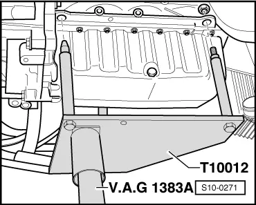
Supporting device -T30099-
t  Hook for T30099 -MP9-200/10 (10-222A/10)-
t  Surface -T30099/1-
  Note
t  The engine is removed downwards together with the gearbox.
t  All cable straps that have been loosened or cut open when the engine was removed must be attached again in the same location when the engine is installed again.
t  Collect drained coolant in a clean container for proper disposal or reuse.
  Caution
When undertaking all installation work, particularly in the engine compartment because of its cramped construction, please observe the following:
t  Lay lines of all kinds (e.g. for fuel, hydraulic fluid, cooling fluid and refrigerant, brake fluid, vacuum) and electrical lines in such a way that the original line guide is re-established.
t  In order to avoid damage to the cables, ensure that there is adequate free access to all moving or hot components.
Observe all safety measures and notes for assembly work on the fuel supply and injection system, at the charge air system and observe as well the rules for cleanliness → Chapter, → Chapter, → Chapter, → Chapter, → Chapter.
   
–  Lift the engine cover at the sides -arrows 1- and pull out towards the front -arrow 2-.
–  Remove air filter and intake air duct → Chapter.
  WARNING
Observe measures when disconnecting the battery → Electrical System; Rep. Gr.27.
–  Remove battery and battery tray → Electrical System; Rep. Gr.27.
–  Remove cover and bulkhead plenum chamber → Body Work; Rep. Gr.66.
–  Remove both front wheels → Chassis; Rep. Gr.44.
–  Remove the sound dampening system → Body Work; Rep. Gr.50.
–  Remove the front right and left wheelhouse liner → Body Work; Rep. Gr.66.
  WARNING
Hot steam or hot coolant may escape when the compensation bottle is opened. Cover the cap with a cloth and open carefully.
–  Drain coolant → Chapter.
  WARNING
t  On vehicles with engine with unit injectors, the temperature of the fuel lines or of the fuel can be up to 100 °C in an extreme case. Let the fuel cool down before opening the lines, as otherwise there is a high risk of burning.
t  Wear protective gloves.
t  Wear safety goggles.
  S10-0209
–  Detach coolant hose, fuel intake hose -2- and fuel return-flow hose -1- from pipes at cylinder head.
For vehicles manufactured up to 08.05
  S10-0359
–  Unlatch fuses, remove fuel filter with its connected lines upwards from bracket -arrow- and lay to the side.
For vehicles manufactured as of 08.05
  S10-0305
–  Release screw -1- by one turn.
–  Release screw -2- and nut -3-.
–  Take out fuel filter with connected hoses and lay to the side.
Continued for all vehicles
  Note
Mark the direction of rotation with chalk or a felt-tip pen before removing the V-ribbed belt. Reversing the rotation direction of an already used belt may destroy it.
–  Remove V-ribbed belt → Chapter.
–  Remove alternator → Electrical System; Rep. Gr.27.
On vehicles with air conditioning
  WARNING
Do not open the refrigerant circuit of the air conditioning system.
  Note
In order to avoid damage to the AC compressor as well as to the refrigerant lines and hoses, ensure that the lines and hoses are not over-tensioned, kinked or bent.
–  Remove AC compressor and holder for auxiliary units → Heating, Air Conditioning; Rep. Gr.87.
–  Tie up removed AC compressor with connected refrigerant hoses to the body.
Continued for all vehicles
–  Remove charge air hoses and charge air pipe between engine and charge air cooler:
t  Engine identification characters BJB, BKC, BXE → Chapter.
t  Engine identification characters BLS → Chapter.
–  Remove fan shroud and radiator → Chapter.
On vehicles with auxiliary heating.
–  Seperate coolant hoses on the auxiliary heating.
–  Remove exhaust pipe of auxiliary heating (only for vehicles with extended exhaust pipe) → Heating, Air Conditioning; Rep. Gr.82.
Continued for all vehicles
–  Remove drive shaft to the right → Chassis; Rep. Gr.40.
–  Unscrew left drive shaft from the flange shaft of the gearbox and tie up.
  A20-10245
–  Torque screws -1 ... 3- release and remove pendulum support.
On four-wheel drive vehicles
–  Remove the assembly carrier → Chassis; Rep. Gr.40.
–  Remove propshaft from gearbox → Chassis; Rep. Gr.39.
Continued for all vehicles
  Note
The decoupling element in the pre-exhaust pipe should not be bent by more than 10° - risk of damage.
–  Remove the pre-exhaust pipe from the exhaust turbocharger → Chapter, → Chapter.
  S10-0269
–  Unlatch the fuse and disconnect the plug from the engine control unit, open the cable guides -arrows-, remove the engine wiring harness and lay to the side.
–  Release all remaining plugs at engine and gearbox and lay aside the relevant lines.
–  Unclamp all connecting, coolant, vacuum and suction hoses from the engine.
–  Remove shift mechanism from gearbox → Chassis; Rep. Gr.34.
–  Remove hydraulic clutch control from gearbox → Chassis; Rep. Gr.34.
  WARNING
After removing the slave cylinder or after separating the hydraulic line, do not depress the clutch pedal.
  S10-0245
–  Screw on -T10012- engine mount to the cylinder block with fixing nut and bolt. Tighten screw M10 x 25/8.8 to approx. 40 Nm.
–  Insert engine/gearbox jack (e.g. -V.A.G 1383/A-) into engine mount -T10012- and slightly raise.
  Note
Use double ladder (e.g. -VAS 5085-) to release the screws for the assembly bracket.
  S10-0271
–  Screw out successively screws for assembly bracket at engine -arrows- ...
  S10-0267
–  …  and at gearbox 0A4 -arrows- or ...
  S10-0268
–  …  at gearbox 02Q -arrows- or ...
  S34-0875
–  ... at gearbox 02E -2-.
  Note
t  Check whether all hose and line connections between engine, gearbox and body are released.
t  When lowering carefully guide the engine/gearbox jack unit, in order to avoid damage.
t  Ensure adequate clearance to the AC compressor, or especially ensure free passage between drive shaft and turbocharger.
–  First of all slightly lower the engine/gearbox unit. Then push engine/gearbox unit forwards and only then lower further.
–  Remove the gearbox from the engine → gearbox; Rep. Gr.34.
  S37-0220

Securing the engine to the assembly stand > < Removing and installing engine