skoda Workshop Repair Guides

Skoda Workshop Service and Repair Manuals

Removing and installing the cylinder head (Octavia II)|Install > < Removing and installing the cylinder head (Octavia II)
Removing
Removing
Requirements
l  
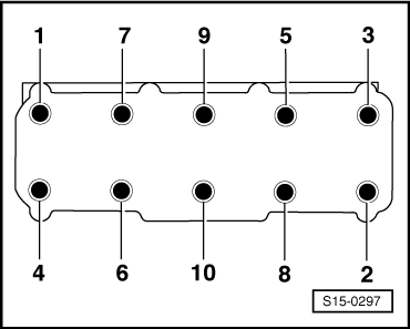
Engine temperature should not exceed 35°C, because the cylinder head could be twisted when slackening the screws.
l  The pistons must not be in TDC.
–  Switch off ignition and withdraw ignition key.
–  Remove engine cover → Chapter.
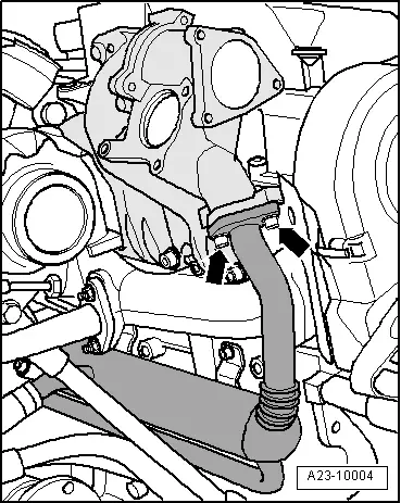
–  Remove air filter, charge air pipes and charge air hoses → Chapter.
t  Engine identification characters BJB, BKC, BXE → Chapter.
t  Engine identification characters BLS → Chapter.
–  Remove the middle sound dampening system → Body Work; Rep. Gr.50.
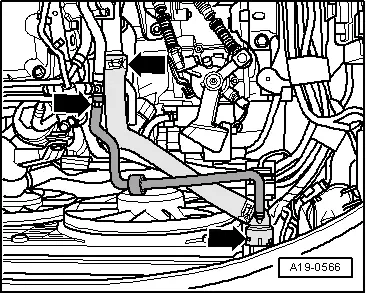
–  Position drip tray e.g. -VAS 6208 - under the engine.
  WARNING
Hot steam or hot coolant may escape when the compensation bottle is opened. Cover the cap with a cloth and open carefully.
–  Drain coolant → Chapter.
   
–  Remove coolant hose between engine and radiator -arrows-.
–  Use hand vacuum pump to extract the fuel at the return-flow hose of the tandem pump → Chapter.
  A19-0566
–  Detach the fuel intake hose -2- and the fuel return hose -1- from the fuel lines.
–  Remove coolant hose -3-.
For engine with identification characters BJB, BKC, BXE
–  Remove pre-exhaust pipe → Chapter, → Chapter.
  A10-10371
–  Release screws -1- and -2- and remove bracket for turbocharger.
  Note
Collect any engine oil which flows out with a cloth.
–  Remove the oil return line -3- at the cylinder block.
–  Unscrew oil feed line from turbocharger, exhaust manifold and from coolant pipe and lay it to one side.
For engine with engine code BLS
–  Remove the air guide pipe between the exhaust turbocharger and the charge air cooler → Chapter.
For vehicles with auxiliary heating
–  Disconnect the fuel feed line.
For engine with engine code BLS
–  Remove pre-exhaust pipe with diesel particle filter → Chapter, → Chapter.
  Note
On four-wheel drive vehicles the pre-exhaust pipe with diesel particle filter can remain in the engine compartment and the angle gearbox must not be removed.
  S21-0076
–  Disconnect plug connection at changeover valve for radiator of exhaust gas recirculation -N345--arrow-.
  A26-10193
–  Detach vacuum hose -2- from vacuum setting element for charge pressure control.
–  Disconnect vacuum hose -3- at the cable for vacuum setting element of the recirculation flap for exhaust gas recirculation.
–  Disconnect vacuum line at the tandem pump.
–  Slacken changeover valve for radiator of exhaust gas recirculation -N345- at bracket.
–  Lay changeover valve for radiator of exhaust gas recirculation -N345- with connected hoses to the side.
–  Detach oil intake hose -1- from exhaust turbocharger.
–  Remove oil feed pipe.
  A21-10062
–  Pull the vacuum hose -arrow- off the brake servo unit.
  A10-10031
–  Remove coolant hose -arrow- at coolant connection fitting.
–  Disconnect the plug from the coolant temperature sender -G62- and detach the electrical wiring
–  Unscrew the fixing screws for oil dipstick guide tube, pull out oil dipstick guide tube to the top out of the cylinder block.
  A19-10066
–  Disconnect coolant hose -1- at exhaust gas recirculation radiator.
–  Remove connection pipe for exhaust gas recirculation radiator -arrows-.
  A26-10191
For four-wheel drive vehicles with engine identification characters BLS
–  Unscrew screw for right flange shaft -arrow 1-.
–  Remove right flange shaft → Gearbox; Rep. Gr.39.
  S34-1047
–  Release screws -1-, screw -2- and the hollow screw -3-.
–  Remove support for exhaust turbocharger with oil return line.
  A21-10088
–  Unscrew screws out of the flange between the radiator for exhaust gas recirculation and the intake mainfold -arrows-.
For vehicles with auxiliary heating
–  Remove exhaust pipe of auxiliary heating (only for vehicles with extended exhaust pipe) → Heating, Air Conditioning; Rep. Gr.82.
–  Remove coolant pipe to auxiliary heating with connected coolant hoses at cylinder block.
For all vehicles
–  Removing toothed belt → Chapter.
–  Remove camshaft sprocket and hub → Chapter.
  A23-10004
–  Remove toothed belt tensioning pulley.
–  Screw out screw -3- and remove Hall sender -G40- from cylinder head.
–  Disconnect all remaining plug connections at cylinder head and lay aside the electrical lines.
–  Separate all remaining coolant, charge air and vacuum hoses and pipes from the cylinder.
–  Release screws -2...4-.
Except vehicles manufactured during the period of time from 05.05 to 05.07
  S15-0451
–  Install -T10014- bracket. Tighten screw for bracket to 20 Nm.
–  Support engine from underneath.
–  Offset hook -MP9-200/10 (10-222A/10) - for supporting device -T30099- from the right lifting eye of the engine into the lug of the bracket -T10014- and preload engine via the spindle, do not lift.
For all vehicles
–  Remove cylinder head cover → Chapter.
  S15-0473
–  Follow the specified order for loosening cylinder head bolts.
–  Carefully raise cylinder head with lifting device -MP9-201 (2024 A)- and workshop crane -VAS 6100-.
  S15-0297

Removing and installing the cylinder head (Octavia II)|Install > < Removing and installing the cylinder head (Octavia II)