skoda Workshop Repair Guides

Skoda Workshop Service and Repair Manuals

Valve dimensions (Superb II, Octavia II, Fabia II, Roomster) > < Testing hydraulic bucket tappets (Superb II, Octavia II, Fabia II, Roomster)
Replacing the valve stem seals on the installed cylinder head (Superb II, Octavia II, Fabia II, Roomster)
Special tools and workshop equipment required
t  
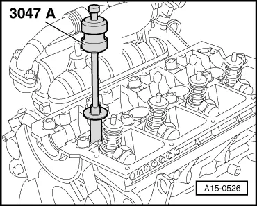
Valve stem seal extractor -MP1-206 (3047 A)-
t  
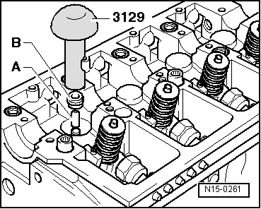
Valve stem seal insertion tool -MP1-212 (3129)-
t  
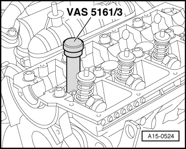
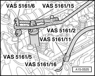
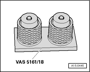
Disassembly and assembly device for valve collets -VAS 5161-
  Note
t  On engines with identification characters BJB, BLS and BXE, those ceramic glow plugs which are marked with a white or silvery painted gasket ring can be installed.
t  Metal glow plugs have a red or green gasket ring.
  Caution
Pay attention to safety instructions when handling ceramic glow plugs → Chapter.
Removing
–  Remove the camshaft Superb II → Chapter, Octavia II → Chapter, Fabia II → Chapter, Roomster → Chapter.
–  Remove bearing shells of camshaft from the cylinder head.
  Note
t  Do not exchange the used bearing shells of the camshaft, mark them for reinstalling.
t  When installing again, mark the assignment of the hydraulic bucket tappets.
–  Remove the hydraulic bucket tappets from the cylinder head and place on a clean surface with the contact surface facing down.
   
–  Insert the impact mandrel -VAS 5161/3- into the guide of the bucket tappet.
–  If valve collets are tight, they must be slackened on all valves by applying slight blows with a rubber-headed hammer.
–  Remove all glow plugs.
t  Metal glow plugs → Chapter.
t  Ceramic glow plugs → Chapter.
Procedure when replacing
–  Put the piston of the relevant cylinder at “bottom dead centre”.
  A15-0524
–  Screw adapter -VAS 5161/11 - into the threaded hole of the glow plug by hand.
–  Screw the interlocking fork -VAS 5161/5- with connected detent part -VAS 5161/6- into the threaded bore M6 on the cylinder head.
–  Insert the guide bushing -VAS 5161/16- into the guide of the bucket tappet of the removed valve up to the stop.
l  Fitting position of the guide bushing: with knurled surface at right angles in the direction of travel.
–  Insert the assembly cartridge -VAS 5161/15- into the guide bushing -VAS 5161/16-.
–  Connect the adapter -VAS 5161/11 - to the compressed air with a commercially available intermediate piece and apply constant pressure.
l  Minimum pressure: 0.6 MPa (6 bar)
–  Hook the pressure fork -VAS 5161/2- onto the detent part -VAS 5161/6- and push the assembly cartridge -VAS 5161/15- downwards.
–  Turn simultaneously the knurled screw of the assembly cartridge to the right, until the tips lock into the gaps between the valve collets.
–  Slightly move the knurled screw of the assembly cartridge back and forward, by doing so the valve collets are pressed apart and are installed in the assembly cartridge.
–  Release the pressure fork.
–  Remove assembly cartridge -VAS 5161/15- and guide bushing -VAS 5161/16-.
–  Remove the valve spring retainer and the valve springs.
  A15-0525
–  Pull off valve stem seal with extractor for valve stem seal -MP1-206 (3047 A)-.
  Note
Each new valve stem seal has a plastic protective sleeve -A-.
  A15-0526
–  To avoid damaging the new valve stem seal -B-, fit a plastic bushing -A- on the valve stem.
–  Lightly oil sealing lip of the new valve stem seal.
–  Slide the valve stem seal onto the plastic bushing.
–  Carefully press the valve stem seal with the valve stem seal insertion tool -MP1-212 (3129)- onto the valve guide.
–  Remove plastic sleeve.
–  Position valve springs and valve spring retainer.
  Note
  N15-0261
If the valve collets were removed from the assembly cartridge, first of all they must be inserted into the insertion device -VAS 5161/18-.
l  The large diameter of the valve collets points to the top.
–  Press assembly cartridge -VAS 5161/15- from the top onto the insertion device -VAS 5161/18- and lift up the valve collets.
  A15-0445
–  Insert the assembly cartridge -VAS 5161/15- again into the guide bushing -VAS 5161/16-.
–  Press down the pressure fork -VAS 5161/2- and turn the knurled screw to the left while pulling it upwards, by doing so the valve collets are inserted.
–  Release the pressure fork -VAS 5161/2- on tightened knurled screw.
–  Repeat this procedure for each valve.
Install
Installation is performed in the reverse order, pay attention to the following points:
–  Insert the hydraulic bucket tappets into the cylinder head.
–  Install the camshaft Superb II → Chapter, Octavia II → Chapter, Fabia II → Chapter, Roomster → Chapter.
  Caution
Pay attention to safety instructions when handling ceramic glow plugs → Chapter.
–  Install glow plugs:
t  Metal glow plugs → Chapter.
t  Ceramic glow plugs → Chapter.
  Note
t  After installing the camshaft, the engine must not be started for about 30 minutes. The hydraulic bucket tappets must settle (otherwise valves would strike the pistons).
t  After carrying out work on the valve gear, carefully crank engine at least 2 revolutions to ensure that no valve touches the piston when the engine is started.
  A15-0525

Valve dimensions (Superb II, Octavia II, Fabia II, Roomster) > < Testing hydraulic bucket tappets (Superb II, Octavia II, Fabia II, Roomster)