
Octavia Mk2
|
| A - | Diesel direct injection system relay -J322- |
| q | on the additional relay carrier under the E-box (R4) |
| B - | Automatic glow period control unit -J179- |
| q | on the additional relay carrier under the E-box (R2) |
| C - | Fuel pump relay -J17- |
| q | on the additional relay carrier under the dash panel (D4.1) |
| D - | Accelerator pedal position sender -G79- and accelerator pedal position sender 2 -G185- |
| q | in the footwell in the accelerator pedal module |
| E - | Brake light switch -F- and brake pedal switch -F47- |
| q | in footwell on the brake pedal |
| F - | Clutch position sender -G476- |
| q | in the engine compartment on the slave cylinder |
| G - | Engine speed sender -G28- |
| q | at cylinder block behind flywheel |
| q | removing and installing → Chapter |
| H - | Oil level and oil temperature sender -G266- |
| q | at the engine oil pan |
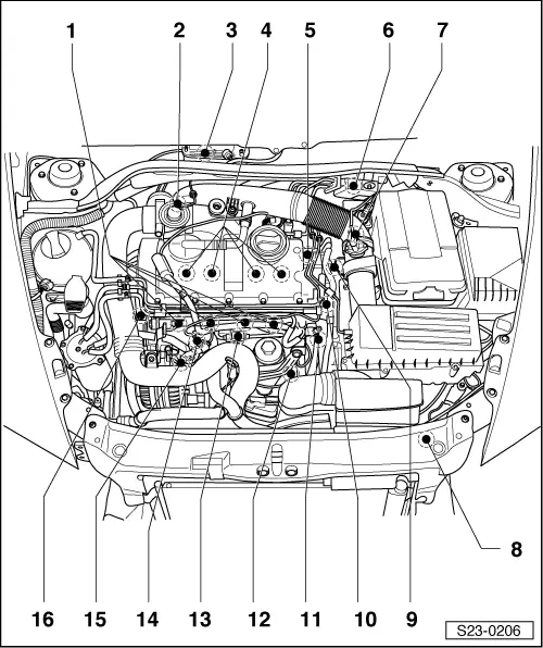
| 1 - | Glow plugs 1 -Q11-, 2 -Q12-, 3 -Q13- and 4 -Q14- |
| q | removing and installing: |
| t | Metal glow plugs → Chapter. |
| t | Ceramic glow plugs → Chapter. |
| q | test: |
| t | Metal glow plugs → Chapter. |
| t | Ceramic glow plugs → Chapter. |
| 2 - | Inlet connection |
| q | with mechanical exhaust gas recirculation valve |
| q | with an intake manifold flap |
| 3 - | Engine control unit -J248 - |
| q | with altitude sender -F96- |
| 4 - | Unit injectors -N240 -, -N241-, -N242- and -N243 - |
| q | under cylinder head cover |
| q | removing and installing, setting → Chapter |
| 5 - | Coolant temperature sender -G62- |
| 6 - | Valve block |
| q | Component parts of the valve block are: |
| t | Changeover valve for intake manifold flap -N239- |
| t | Exhaust gas return valve -N18- |
| t | Solenoid valve for charge pressure control -N75- |
| 7 - | Air mass meter -G70- |
| 8 - | Coolant temperature sender at radiator outlet -G83 - |
| 9 - | Tandem pump |
| 10 - | Connector |
| q | Central plug connection for unit injectors -N240-, -N241-, -N242- and -N243-. |
| 11 - | Fuel temperature sender -G81- |
| 12 - | Connector |
| q | for engine speed sender -G28- |
| 13 - | Connector |
| q | for hall sender -G40- |
| 14 - | Vacuum reservoir |
| 15 - | Charge pressure sender -G31- with intake air temperature sender -G42- |
| 16 - | Hall sender -G40- |
| q | under top toothed belt guard |
| q | removing and installing → Chapter |