| –
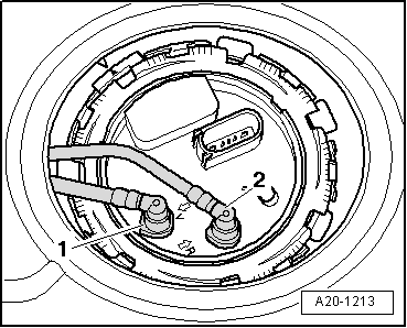
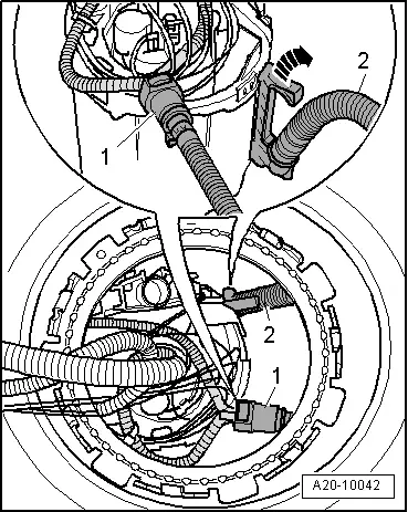
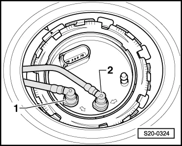
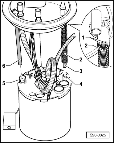
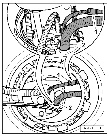
| Separate through the opening of the fuel tank the fuel line -1- to the suction jet pump, to do so press the release button. |
| –
| Separate the fuel delivery line -2- from the fuel delivery unit. |

Note | t
| You must wear protective gloves for removing the fuel delivery unit. |
| t
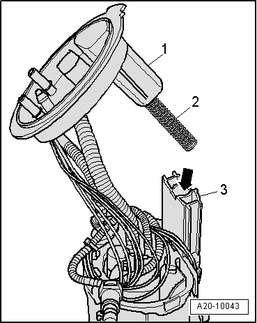
| Take the fuel delivery unit out of the fuel tank in such a way that the electrical cables and the fuel hoses are not damaged and that the float arm of the sender for the fuel gauge display -G- is not bent. |
| t
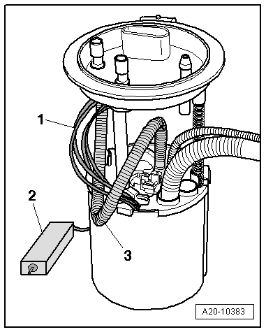
| You must empty the old delivery unit before disposing of it if you wish to replace the fuel delivery unit. |
| –
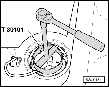
| Pull the fuel delivery unit out of the opening of the fuel tank. |
| The fuel delivery unit is installed in the reverse order. However, pay attention to the following: |
| –
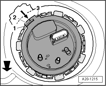
| Insert the fuel delivery unit into the fuel tank with the closing flange placed to the side. Thus, do not bend the float arm of the fuel gauge sender unit -G-. |
| –
| Install the fuel delivery unit and the fuel line. |
| –
| Insert the new dry gasket ring into the opening of the fuel tank and moisten only from the inside with fuel for installing the closing flange. |
| Fuel delivery unit type one |
|
|
|