skoda Workshop Repair Guides

Skoda Workshop Service and Repair Manuals

Removing and installing the camshaft adjuster > < Valve gear - part 2
Replacing exhaust camshaft seal
Special tools and workshop equipment required
t  Supporting device -T30099-
t  Gasket ring extractor -MP1-215 (2085)-
t  Adapter -MP1-215/2 (2085/2)-
t  Counterholder -MP1-216 (3036)-
t  Assembly device -T10071-
t  Thrust piece -T10353-
t  Two-arm extractor -T40001- with claw -T40001/6- and claw -T40001/7 -
Removing
–  Removing the toothed belt:
t  Engines without split toothed belt guard → Chapter.
t  Engines with split toothed belt guard → Chapter.
   
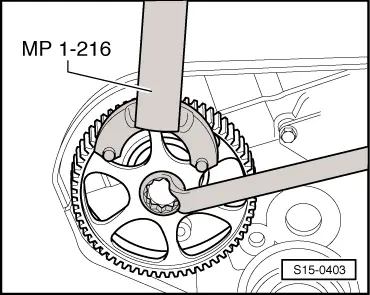
–  Slacken screw from camshaft sprocket. Use counterholder -MP1-216- for this purpose.
  S15-0403
–  Release screw from camshaft sprocket approx. 10 mm -arrow-.
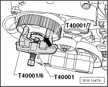
–  Detach camshaft sprocket with extractor -T40001-, claw -T40001/6- and claw -T40001/7-.
–  Remove the fixing screw and the screw for camshaft sprocket.
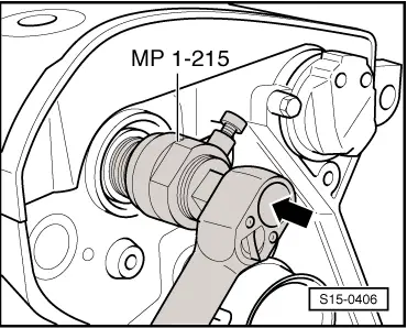
–  Screw in the adapter -2085/2- by hand up to the stop in the crankshaft to guide the gasket ring extractor.
–  Turn inner part of gasket ring extractor -MP1-215- two turns (approx. 3 mm) out of the outer part and lock with knurled screw.
  N15-10476
–  Oil the thread head of the gasket ring extractor -MP1-215-, position and forcefully screw it into the gasket ring as far as possible.
–  Release knurled screw and turn the inner side against the camshaft until the gasket ring is pulled out.
–  Clamp gasket ring extractor into the vice at the flats. Remove gasket ring with pliers.
Install
  Note
Do not oil the sealing lip of the gasket ring.
–  Remove oil residue on the camshaft stud with a clean cloth.
–  Cover the slot on the exhaust camshaft cone with adhesive tape and carefully push the dry gasket ring onto the camshaft.
  S15-0406
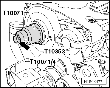
–  Press in the gasket ring with the pressure bushing -T10071-, the thrust piece -T10353- and a washer -arrow- up to the stop. Use the screw -T10071/4- for this purpose.
  Note
t  When rotating the camshaft, the pistons must not be positioned at TDC. Risk of damaging valves and pistons.
t  Ensure that the parallel key is correctly positioned.
–  Insert parallel key into camshaft.
  N15-10477
t  Observe the fitting position of the camshaft sprocket: The small stay on the camshaft sprocket points outwards -arrows- and the TDC marking is visible on the cylinder 1.
  S13-0620
–  Install camshaft timing gear. Hold the camshaft sprocket tight with the counterholder -MP1-216- for tightening the new screw.
   Tightening torque: 50 Nm + torque a further 180° (1/2 turn).
Further installation occurs in a similar way in reverse order to removal.
  S15-0403

Removing and installing the camshaft adjuster > < Valve gear - part 2