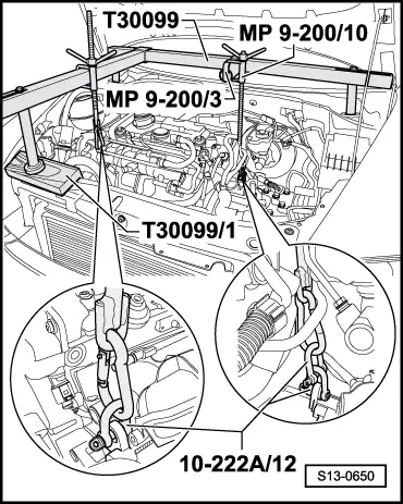
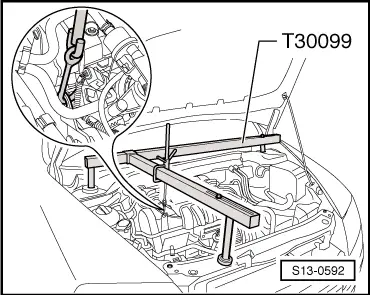
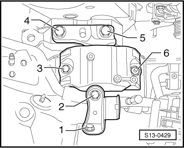
Note | To remove the engine support, the engine must be raised relatively high with the supporting device -T30099-. It is necessary to remove the drive shafts from the gearbox in order to avoid damage to the drive shafts through the sharp bending angle. |
Note | t
| Safety precautions when working on the fuel supply system → Chapter. |
| t
| Rules of cleanliness when working on the fuel supply system → Chapter. |
| –
| Switch off the ignition and all electrical components and take out the ignition key. |
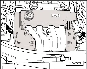
| Vehicles with engine identification characters BLR, BLX, BLY, BVX, BVY, BVZ |
|
|
|

 WARNING
 Caution