skoda Workshop Repair Guides

Skoda Workshop Service and Repair Manuals

Removing and installing pressure box for exhaust turbocharger > < Testing exhaust turbocharger pressure box
Removing and installing exhaust gas turbocharger
Special tools and workshop equipment required
t  Pliers for spring strap clamps
t  Tensioning strap -T10038-
  Caution
In case a mechanical damage to the exhaust gas turbocharger is found, e.g. damage to the compressor wheel, it is not sufficient to only replace the turbocharger. In order to avoid consequential damage, perform the following tasks:
t  Clean all oil lines.
t  Change engine oil and oil filter.
t  Inspect the air filter housing, the air filter element and the intake hoses for contaminations.
t  Inspect the whole charge-air routing and the charge air cooler for foreign bodies.
If foreign bodies are detected in the charge air system, the complete charge-air routing must be cleaned and if necessary the charge air cooler must also be replaced.
Removing
–  Remove engine cover → Chapter.
–  Drain coolant → Chapter.
–  Remove the front part of the front right wheelhouse liner → Body Work; Rep. Gr.66.
   
–  Detach charge air hose -arrow- from charge air cooler.
  A21-10050
–  Release screws -arrows-, unlock the top quick coupling and remove the charge air pipe.
  A21-10030
–  Disconnect plugs -1- and -2-.
  S21-0086
–  Remove and disconnect the plug connection -arrow- for lambda probe upstream of catalytic converter from the bracket and expose wiring loom.
–  Remove the cooling water tank cover → Body Work; Rep. Gr.66.
  A26-10134
–  Remove intermediate wall for the plenum chamber.
  S24-0647
–  Disconnect the plug -1- from the ignition coils and place the wiring harness to the side.
  A15-10137
–  Disconnect the coolant line -arrow- to the expansion reservoir.
  A21-10043
–  Detach coolant hose -1- and -2-.
–  Unscrew coolant line -3-.
  A21-10042
–  Remove shield with coolant pipe -arrows-.
  S21-0088
–  Pull off the thin coolant hose at the top from the upper coolant hose -arrow-.
  A21-10044
–  Remove the valve housing from the cylinder head cover -arrows-.
  A15-10198
–  Release the screws -1- of the line for the crankcase ventilation from the exhaust turbocharger.
–  Open warm-type clamp -2-. Disconnect the line of the crankcase ventilation from the cylinder head cover and remove.
–  Detach the activated charcoal filter system line -3- to the exhaust gas turbocharger from the cylinder head cover.
–  Remove oil feed line -4- from exhaust gas turbocharger.
  A21-10032
–  Release both top fixing nuts -arrows- of the front part of the exhaust gas system/exhaust gas turbocharger.
  N26-10097
–  Unbolt heat shield for right drive shaft -arrows-.
  A10-1633
–  Release both bottom fixing nuts -arrows- of the front part of the exhaust gas system/exhaust gas turbocharger.
  N26-10097
–  Unscrew the hanger for the exhaust system -arrows-.
  A10-1632
–  Separate exhaust system at the clamping sleeve -arrow-.
–  Pull off the front part of the exhaust gas system and push it slightly back.
  Note
The front part of the exhaust gas system is not removed and the lambda probe connector is not disconnected.
  S26-0207
–  Remove pipe -1-.
–  Release the screws -3- and -4- of the coolant feed line.
  S15-0465
–  Remove the oil return-flow line -arrows- at the exhaust gas turbocharger.
  A21-10048
–  Release the screws -1- and -2- and remove the support for exhaust gas turbocharger.
  Note
The following steps are necessary in order to have more space between the cylinder head and the bulkhead.
  A21-10047
–  Release screws -2- and -3-.
  A10-1578
–  Pull the engine with the tensioning strap -T10038- up to the steering gear.
  S21-0085
–  Separate the coolant pipe -arrow-.
  Note
It is not necessary to detach the nuts of the clamping strip.
  A21-10036
–  Unscrew the nuts -arrows-.
  N21-10104
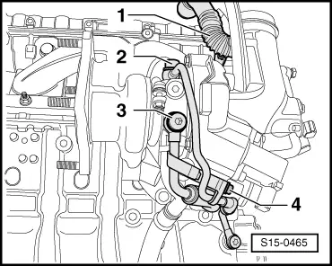
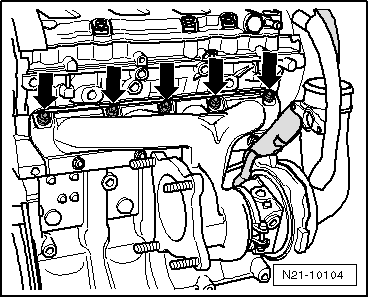
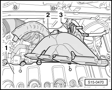
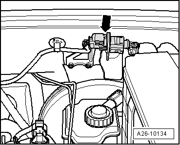
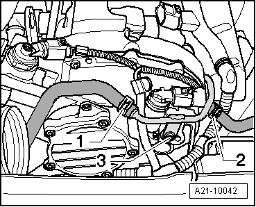
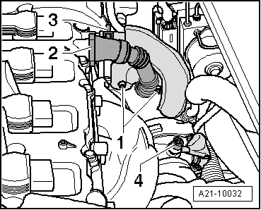
–  Remove the exhaust gas turbocharger/exhaust manifold -2- between the coolant hoses -3- and the cylinder head cover -1- inclined to the top left.
Install
  Caution
In case a mechanical damage to the exhaust gas turbocharger is found, e.g. damage to the compressor wheel, it is not sufficient to only replace the turbocharger. In order to avoid consequential damage, perform the following tasks:
t  Clean all oil lines.
t  Change engine oil and oil filter.
t  Inspect the air filter housing, the air filter element and the intake hoses for contaminations.
t  Inspect the whole charge-air routing and the charge air cooler for foreign bodies.
If foreign bodies are detected in the charge air system, the complete charge-air routing must be cleaned and if necessary the charge air cooler must also be replaced.
Installation is carried out in the reverse order. Pay attention to the following:
t  Gaskets, gasket rings and self-locking nuts must be replaced.
t  Fill the exhaust turbocharger with engine oil at the connection fitting for the oil feed line.
t  After installing the exhaust turbocharger, run engine at idling speed for about 1 minute to ensure that oil is supplied to the exhaust turbocharger.
t  
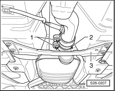
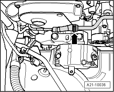
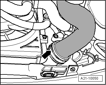
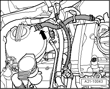
The coolant return flow line ( → Chapter, Pos. 6) must be installed together with the exhaust turbocharger.
t  
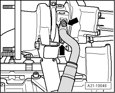
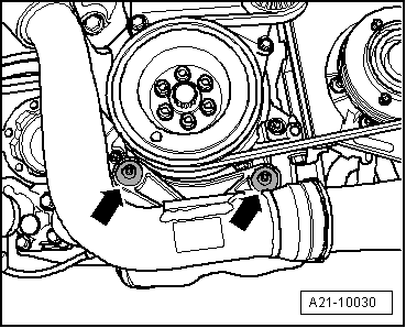
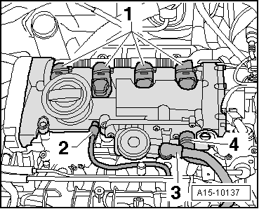
Hose connections and hoses for charge air system must be free of oil and grease before being assembled. The gasket ring and the sealing surface must be slightly oiled only for push-fit couplings → Chapter.
t  Secure all hose connections with hose clamps → Electronic Catalogue of Original Parts.
t  For this step, observe the assembly instruction for hose connections with push-fit couplings → Chapter.
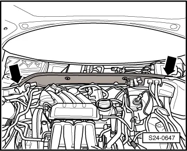
–  Install exhaust system and align free of stress → Chapter.
–  Install pendulum support → Chapter.
–  Top up coolant → Chapter.
Tightening torques → Chapter.
  S15-0470

Removing and installing pressure box for exhaust turbocharger > < Testing exhaust turbocharger pressure box