skoda Workshop Repair Guides

Skoda Workshop Service and Repair Manuals

Removing and installing fuel pressure sender G247 , engine identification characters BLR, BLX, BLY, BVX, BVY, BVZ > < Removing and installing intake manifold, engine identification characters BLR, BLX, BLY, BVX, BVY, BVZ
Removing and installing fuel distributor with intake manifold flaps, engine identification characters BLR, BLX, BLY, BVX, BVY, BVZ
Removing
  WARNING
Release pressure in the high pressure area of the fuel system → Chapter.
–  Removing the intake manifold → Chapter.
   
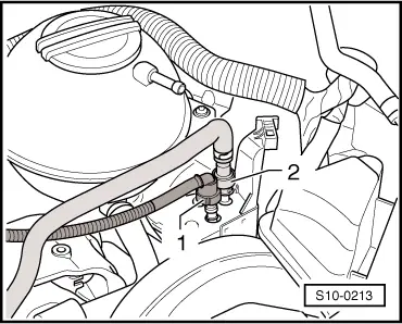
–  Disconnect the fuel feed line -2- (press in the securing ring).
–  Remove fuel hoses.
  S10-0213
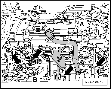
–  Disconnect the plug connections at the fuel distributor -arrows-.
–  Remove pipe for crankcase ventilation -A-.
–  Pull off the oil dipstick with guide tube -B- from the engine.
  Note
When loosening the fuel pipes, counterhold the corresponding screw neck.
  N24-10272
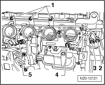
–  Unscrew screws -1- to -5- and remove the fuel pipes.
  N20-10121
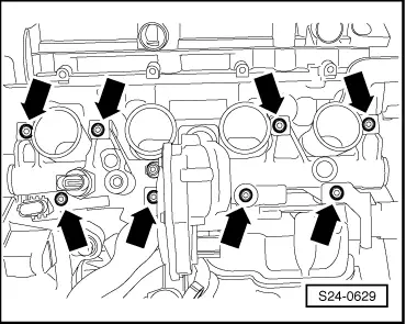
–  Release the fixing screws -arrows- of the fuel distributor.
–  Carefully disconnect the fuel distributor with intake manifold flaps from the injection valves.
Install
Installation is carried out in the reverse order. Pay attention to the following:
t  The plugs must be placed onto the injection valves before installing.
t  If an injection valve was pulled out of the cylinder head during removal of the fuel distributor, the Teflon gasket ring must be replaced → Chapter.
t  Replace O-rings between injection valves and fuel distributor and moisten lightly with clean engine oil.
t  If the fuel distributor was replaced, the intake manifold flap potentiometer -G336- must be adapted to the engine control unit → Vehicle diagnosis, testing and information system VAS 5051.
t  Fit fuel distributor onto the cylinder head and press evenly onto the injection valves.
  S24-0629
–  Tighten the fixing screws -arrows- of the fuel distributor to 10 Nm.
  Note
Before installing the fuel pipes, check the tightening torque of the corresponding screw neck.
t  High pressure connection piece in the high pressure pump: 40 Nm
t  Low pressure connection piece in the high pressure pump: 30 Nm
t  Pressure limiting valve in fuel distributor: 30 Nm
–  Install the fuel pipes with new hollow screws and first of all tighten all the screws by hand.
–  Tighten fixing screws of the high pressure pump to 10 Nm.
  S24-0629
–  Now tighten the screws/union nut -1- to -5- in the following sequence:
1 - Fixing screws -1- to 10°Nm
2 - Hollow screw -2- to 15 Nm
3 - Hollow screw -3- to 15 Nm
4 - Hollow screw -4- to 15 Nm
5 - Union nut -5- to 22 Nm
  N20-10121

Removing and installing fuel pressure sender G247 , engine identification characters BLR, BLX, BLY, BVX, BVY, BVZ > < Removing and installing intake manifold, engine identification characters BLR, BLX, BLY, BVX, BVY, BVZ