skoda Workshop Repair Guides

Skoda Workshop Service and Repair Manuals

Valve dimensions > < Check hydraulic supporting elements
Replacing valve stem seals
l  Cylinder head fitted
Special tools and workshop equipment required
t  Valve stem seal extractor -MP 1-230 (3364)-
t  Valve stem seal insertion tool -MP 1-233 (3365)-
t  Disassembly and assembly device for valve keys -VAS 5161-
t  Guide plate for 2.0 TDI engine -VAS 5161/21-
  Note
t  With cylinder head removed:
t  Remove the ceramic pencil type glow plugs from the cylinder head → Chapter.
t  Remove unit injectors from the cylinder head → Chapter.
t  Position cylinder head on a suitable valve supporting plate.
Removing
–  Remove the camshafts → Chapter.
  Note
t  Ensure that the bearing shells of the camshafts are not mixed up.
t  Mark assignment of the bearing shells for the camshafts with waterproof marker on the reverse side.
–  Remove bearing shells of camshafts from the cylinder head.
–  Remove unit injectors → Chapter.
   
–  Put the piston of the relevant cylinder at “bottom dead centre”.
–  Position the guide plate -VAS 5161/21-1- onto the cylinder head.
–  Attach the guide plate -VAS 5161/21-1- with the knurled screws -VAS 5161/21-4-.
–  Insert the impact drift -VAS 5161/3- into the guide plate and knock off the tightly fitted valve keys using a plastic hammer.
  A15-10090
–  Screw the adapter -VAS 5161/21-2- into the guide plate by hand.
–  Fix the detent part -VAS 5161/6- with the suspension forks -VAS 5161/5- at the cylinder head.
–  Slide the knurled spacer ring -VAS 5161/21-5- onto the assembly cartridge -VAS 5161/8-.
–  Insert the assembly cartridge -VAS 5161/8- into the guide plate -VAS 5161/21-1-.
–  Connect the adapter -VAS 5161/21-2- to the compressed air with a commercially available intermediate piece and apply constant pressure.
l  Minimum pressure: 0.6 MPa (6 bar) overpressure
–  Hook the pressure fork -VAS 5161/2- onto the detent part -VAS 5161/6-.
–  Press the assembly cartridge -VAS 5161/8- downwards and turn simultaneously the knurled screw of the assembly cartridge to the right, until the tips click into the valve keys.
–  Slightly move the knurled screw of the assembly cartridge back and forward. This presses the valve keys apart and installs them into the assembly cartridge.
–  Release the pressure fork -VAS 5161/2-.
–  Remove assembly cartridge -VAS 5161/8- with knurled spacer ring -VAS 5161/21-5-, valve spring retainer and valve spring.
  A15-10006
–  Pull off valve stem seals with extractor for valve stem seal -3364-.
Install
  A15-10007
–  Insert the supplied plastic bushings -B- on the relevant valve stem. This will prevent any damage to the new valve stem seals -A-.
–  Insert the new valve stem seal in the insertion tool for valve stem seal -MP 1-233-.
–  Oil the sealing lip of the valve stem seal and carefully slide it onto the plastic sleeve -B-.
–  Carefully press the valve stem seal with the valve stem seal insertion tool -MP 1-233- onto the valve guide.
–  Take off plastic sleeve again -B-.
–  Insert the valve spring and the valve spring retainer.
  S15-0271
–  If the valve keys were removed from the assembly cartridge -VAS 5161/8-, first of all they must be inserted into the insertion device for valve keys -VAS 5161/18-.
  Note
The large diameter of the valve keys points to the top.
–  Press the assembly cartridge from the top onto the insertion device for valve keys -VAS 5161/18- and raise the valve keys.
  A15-0445
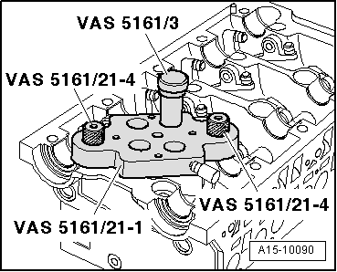
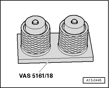
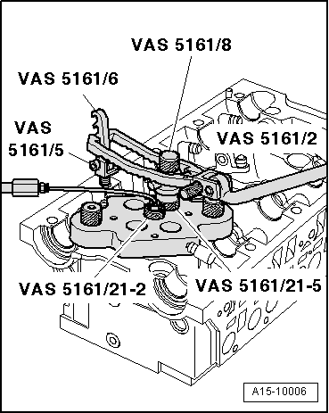
–  Insert the assembly cartridge -VAS 5161/8- into the guide plate.
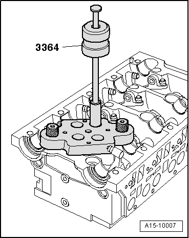
–  Press down the pressure fork -VAS 5161/2-, turn the knurled screw of the assembly cartridge back and forward and while doing so pull it towards the top. Thereby the valve keys are replaced.
–  Release the pressure fork -VAS 5161/2- on tightened knurled screw.
The valve stem seal is removed and installed on the other valves in the same way.
–  Install unit injectors → Chapter.
–  Install camshafts → Chapter.
  Note
t  After installing the camshafts, the engine must not be cranked or started for about 30 minutes. Roller rocker arm with hydraulic valve clearance compensation must settle (otherwise valves would strike the piston).
t  After carrying out work on the valve gear, carefully crank engine at least 2 revolutions to ensure that no valve touches the piston when the engine is started.
  A15-10006

Valve dimensions > < Check hydraulic supporting elements