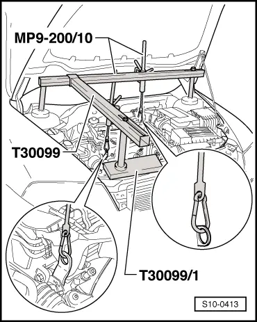
Position supporting device -T30099- and support plate -T30099/1- and support the engine/gearbox unit in its installed position.
–
Uniformly pre-tension the engine/gearbox unit with both spindles, but do not raise.
–
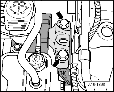
Release the screws -arrows- of the unit mounting at the engine.
–
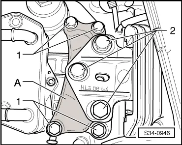
Slightly loosen the screws -2- of the unit mounting at the gearbox (less than 1 revolution).
–
Successively replace all the screws of the unit mounting (as long as it has not already been performed when installing the engine) and screw them in loosely.
–
Move the engine/gearbox unit with a tyre lever between engine support -1- and supporting arm -3- for engine mount until the following dimensions are set:
l
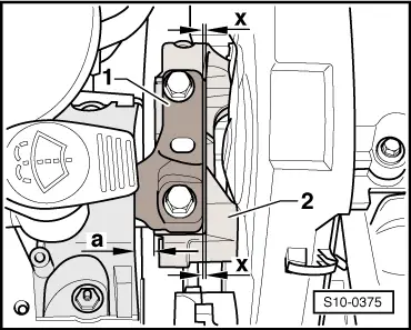
Between engine bracket and engine support there must be a distance -a- of 10 mm.
l
The cast iron edge on the engine support -2- must be parallel to the supporting arm -1- the dimension -x- must be the same at the front and rear.
Note
The distance -a- = 10 mm can be checked e.g. with suitable round bars.
–
Tighten the screws of the unit mounting for engine → Chapter.
–
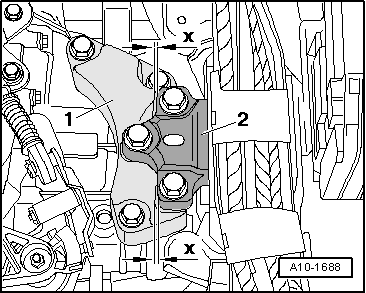
Make sure that on the gearbox side the edges of the supporting arm -2- and gearbox support -1- are parallel.
l
The dimension -x- must be the same on both mount sides.
–
Tighten the screws of the unit mounting for gearbox → Chapter.
 Note
Note