skoda Workshop Repair Guides

Skoda Workshop Service and Repair Manuals

Testing compression pressure for engine with engine identification characters BKD, AZV > < Removing
Install
Install
  Note
t  There must not be any oil or coolant present in the blind holes for the cylinder head bolts.
t  Replace cylinder head bolts.
t  When performing installation work replace the self-locking nuts.
t  Replace screws which have been tightened to a turning angle as well as gasket rings and seals.
t  Remove the new cylinder head seal from its wrapping immediately before fitting.
t  Treat the seal with the utmost care. Damage to the silicone layer and in the area of the bead results in leakages.
t  When installing an exchange cylinder head with the camshafts installed, it is necessary to oil the contact surfaces between the roller arms and the cams after installing the cylinder head.
t  The plastic base for protecting the open valves should only be removed immediately before attaching the cylinder head.
t  Secure all hose connections with corresponding hose clips.
  WARNING
Wear protective gloves when working with sealant and grease remover!
–  Make sure that when cleaning the cylinder head and cylinder block no impurities can get into the cylinder or into the oil and coolant galleries.
–  Carefully remove old residual sealant from the cylinder head/cylinder block using a chemical sealant remover.
–  Before fitting the cylinder head rotate the crankshaft so that all the pistons are almost evenly at TDC.
   
–  Pay attention to the identification of the cylinder head seal.
t  Part number = -arrow 1-
t  Control code = -arrow 2- (ignore)
t  Bores = -arrow 3-
  Note
t  If the cylinder head gasket or cylinder head are replaced, then install a new cylinder head gasket with the same identification -arrow 3-.
t  If parts of the crankshaft drive were replaced then the new cylinder head gasket must be defined by measuring the protrusion of the pistons in TDC .
  S15-0438
–  Fit on cylinder head gasket.
l  Pay attention to dowel sleeves -arrows- in cylinder block.
l  Observe the installed position of the cylinder head gasket, the marking “above” or the part number must point to the cylinder head.
–  Insert the cylinder head.
  S15-0437
–  Insert new cylinder head bolts and tighten by hand.
–  Tighten the cylinder head in four stages in the indicated tightening sequence:
  S15-0444
StageTighten
I
–  Pre-tighten with the torque wrench to 40 Nm.
II
–  Pre-tighten with the torque wrench to 60 Nm.
III
–  Using a rigid wrench torque a further 90° (1/4 turn).
IV
–  Using a rigid wrench torque a further 90° (1/4 turn).

  Note
Tightening up the cylinder head bolts after doing repair work is not necessary.
   
–  Before inserting the valve-lever shaft, check whether all the ball studs -1- and O-rings -2- are inserted in the unit injectors.
  S15-0446
–  Screw on valve-lever shaft and bearing frame as follows:
–  Replace screws -1...5-.
  S15-0442
SequenceTighten
I
–  Tighten screws -2- and -4- alternately in stages, until the valve-lever shaft is positioned on the bearing frame.
II
–  Tighten screws -1-, -3- and -5- to 20 Nm + torque a further 90° (1/4 turn).
III
–  Tighten screws -2- and -4- to 20 Nm + torque a further 90° (1/4 turn).
IV
–  Tighten bearing frame screws -6…10- to 20 Nm.

   
–  Insert screws -2...5- with spread on locking agent -D 000 600 A2- and tighten to 10 Nm.
–  Screw in the pin screw -1- and tighten to 10 Nm.
  A15-10353
–  Position hub onto exhaust camshaft.
–  Tighten screw -1- to 100 Nm, use counterholder -T10051- to hold.
–  Fit the hub onto the inlet camshaft in the same way and tighten.
  A15-0931
–  Push camshaft sprockets onto hubs.
l  Both tooth segments -arrows- of the camshaft sprockets must be facing up.
–  Slightly screw in plug -1-.
l  It must still be possible to turn the camshaft sprockets on the hubs, however they must not hang loose.
–  Lock hubs with locking pins -3359-.
–  Rotate crankshaft to TDC for cylinder 1.
  S15-0445
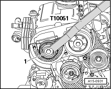
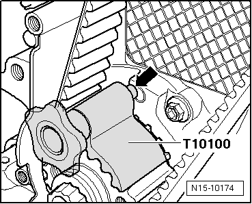
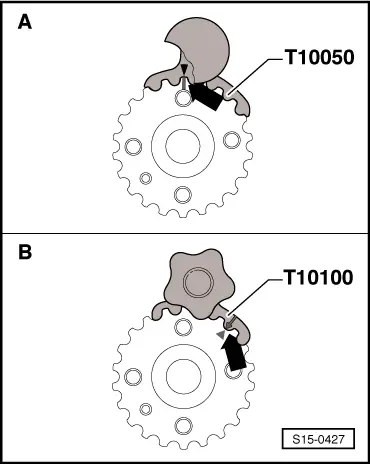
–  Depending on the version of the toothed belt sprocket, lock the crankshaft with the crankshaft arrester -T10050- or the crankshaft arrester -T10100-.
Difference of the toothed belt sprocket of crankshaft:
A = original version of toothed belt sprocket with circular tooth flank, rectangular TDC marking for cylinder 1 at tooth in 12 o'clock position - use crankshaft arrester -T10050-.
B = new version of toothed belt sprocket with eliptical tooth flank, triangular TDC marking for cylinder 1 at tooth opening in 1 o'clock position - use crankshaft arrester -T10100-.
  Note
t  The markings on the toothed belt sprocket and on the crankshaft arrester must be in line with each other -arrow-.
  S15-0427
t  The stud of the crankshaft arrester -arrow- must engage at the same time in the hole of the sealing flange.
t  The crankshaft arrester can only be fitted onto the toothed belt sprocket from the front side of the serration.
–  install (set the timing) → Chapter.
–  Install cylinder head cover → Chapter.
Further installation occurs in reverse order to removal. Pay attention to the following:
–  Connect oil lines to exhaust turbocharger and install exhaust turbocharger support.
–  Install exhaust system → Chapter.
–  Align exhaust system free of stress → Chapter.
–  Checking the oil level → Octavia II.
  Note
Change contaminated engine oil → Octavia II.
–  Top up coolant → Chapter.
  N15-10174

Testing compression pressure for engine with engine identification characters BKD, AZV > < Removing