
Octavia Mk2
| Summary of components for engine with engine identification characters BKD, AZV |
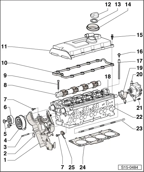
| 1 - | Rear toothed belt guard |
| 2 - | Rubber grommet |
| q | replace if damaged |
| 3 - | Pin screw - 10 Nm |
| 4 - | Hub |
| q | for inlet camshaft with rotor for hall sender -G40- |
| q | to remove use extractor -T10052- |
| 5 - | 100 Nm |
| q | to release and tighten use counterholder -T10051- |
| 6 - | Hub |
| q | for exhaust camshaft |
| q | to remove use extractor -T10052- |
| 7 - | 10 Nm |
| q | insert using locking agent -D 000 600 A2- |
| 8 - | Valve-lever shaft |
| q | Mark the installation position of the valve lever |
| q | do not interchange |
| q | removing and installing → Chapter |
| q | before inserting, check whether all the ball studs and O-rings are inserted in the unit injectors |
| 9 - | 20 Nm + torque a further 90° (1/4 turn) |
| q | replace |
| q | pay attention to order for slackening → Chapter |
| q | pay attention to order and procedure for tightening → Chapter |
| 10 - | Gasket for cylinder head cover |
| q | replace if damaged or leaking |
| q | press onto the spacer sleeves (Position 15) |
| 11 - | Cylinder head cover |
| q | removing and installing → Chapter |
| 12 - | Screw cap |
| 13 - | Gasket |
| q | replace if damaged or leaking |
| 14 - | Sealing sleeve |
| 15 - | Screw with spacer sleeve, 10 Nm |
| q | pay attention to sequence for loosening and tightening → Chapter |
| 16 - | 20 Nm |
| 17 - | Cylinder head bolt |
| q | replace |
| q | pay attention to order for slackening → Chapter |
| q | pay attention to order and procedure for tightening → Anchor |
| 18 - | Multipin plug connection |
| q | central for pump-nozzle units |
| q | when removing, disconnect plug connection from bushing by turning to the left |
| 19 - | Gasket |
| q | replace |
| 20 - | Tandem pump |
| q | removing and installing → Chapter |
| q | check → Chapter |
| 21 - | 20 Nm |
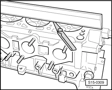
| 22 - | Cylinder head |
| q | removing → Chapter |
| q | check for distortion → Fig. |
| q | installing → Chapter |
| q | after replacing fill entire system with fresh coolant → Chapter |
| 23 - | Mixing tube |
| q | inserted into cylinder head |
| q | pull out with hook |
| q | Fitting position mixing tube → Fig. |
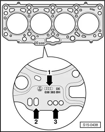
| 24 - | Cylinder head gasket |
| q | replace → Chapter |
| q | Pay attention to the marking → Fig. |
| 25 - | Hall sender -G40- |
| q | for camshaft position |
|
|
 Note
Note
|
|