skoda Workshop Repair Guides

Skoda Workshop Service and Repair Manuals

Removing and installing roller rocker arm for engine with engine identification characters BKD, AZV > < Replace gasket rings of camshafts for engine with engine identification characters BKD, AZV
Removing and installing camshafts for engine with engine identification characters BKD, AZV
Special tools and workshop equipment required
t  Universal dial gauge holder -MP 3-447 (VW 387)-
t  Counterholder -T10051-
t  Extractor -T10052-
t  Rig pin -3359- or rig pin -MP 1-301-
t  Surround -T10262-
t  Dial gauge
t  Silicone sealant -D 176 501 A1-
t  Sealant remover gasket stripper (bearing code GST, bearing article no. R 34402), manufacturer Retech s.r.o.
t  Cleaning agent and grease remover e.g. -D 000 401 04-
t  Protective goggles
t  Protective gloves
Removing
l  Cylinder head attached at engine.
–  Remove engine cover → Chapter.
   
–  Remove air filter with air intake hose and suction hose → Chapter.
–  Remove battery → Electrical System → Rep. Gr.27.
–  Remove plenum chamber bulkhead → Body Work → Rep. Gr.66.
–  Remove radiator for exhaust gas recirculation with radiator flap from bracket → Chapter. The coolant hoses remain connected.
–  Remove bracket of radiator flap for exhaust gas recirculation and bracket of exhaust gas recirculation radiator.
–  Remove the toothed belts from the toothed belt sprockets of camshafts → Chapter.
  S10-0304
–  Remove locking pins -3359-.
–  Screw out screws -1- and -2- of the camshaft sprockets.
–  Remove camshaft sprockets from the hubs.
  N15-0702
–  Loosen fixing screw -1- of the hub. Use counterholder -T10051- for this purpose.
–  Unscrew the fixing bolt of the hub by approx. 2 turns.
  N15-10043
–  Position the extractor -T10052- and align it with the hub bores.
–  Tighten fixing screws -1-.
–  Put the hub under tension by uniformly tightening the screw -2- until the hub is released from the camshaft cone.
  Note
To do so, counterhold on the hexagon of the extractor using a wrench SW 30.
–  Remove hub from cone of camshaft.
–  Remove the hub of the outlet camshaft in the same way.
–  Remove cylinder head cover → Chapter.
–  Remove tandem pump → Chapter.
  Note
The hoses can remain connected to the tandem pump.
  N15-10042
–  Release the counternuts -2- of the adjusting screws -1- on all unit injectors and unscrew the adjusting screws until the relevant valve lever rests against the spring cap of the unit injector.
  Note
Do not pull out screws of valve-lever shaft, so that the individual parts on the valve-lever shaft remain attached. If necessary mark assignment of the valve lever.
  S23-0211
–  Release screws -1--3- and -5-.
–  Loosen screws -2- and -4- and release alternately in several stages. Then remove the valve-lever shaft with the valve levers.
–  Release the top securing screws of the rear toothed belt guard.
  S23-0212
–  Pull release pin in -direction of arrow 1- and open the knurled nut in -direction of arrow 2-.
–  Disconnect central plug for unit injectors and glow plugs and expose wiring loom.
  A15-0912
–  Disconnect plug connections -1- for the unit injectors, at the same time press latch clips together.
  A23-0213
–  Unplug connector -1- of the glow plugs.
  Caution
The disassembly/assembly of the pre-wiring must only be performed by unscrewing/screwing the clamps. Slackening the cable duct from the clamps causes them to bend up and it can lead to cable fracture due to high play.
–  Unscrew fixing screws -2- of the stainless steel clamps (10 Nm) and lay pre-wiring aside.
–  Slacken and unscrew the remaining 15 screws for the bearing frame evenly from the outside to the inside.
–  Release press-off screws SW 15 of the frame -T10262- by turning anti-clockwise upwards up to the stop.
  N23-10094
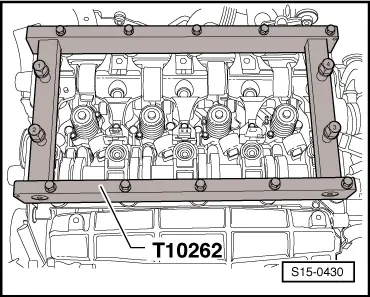
–  Position frame -T10262-, as shown, on the bearing frame and tighten fixing screws SW 10 to 10 Nm.
–  Screw in press-off screws by hand, until these touch the cylinder head screws.
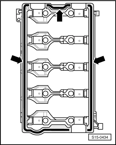
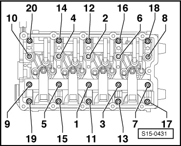
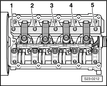
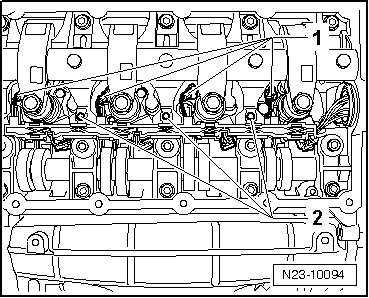
–  Screw in press-off screws evenly in the order -1...4-, which is type-punched on the screw heads, until the bearing frame is being released from the cylinder head.
–  Remove bearing frame.
  Note
t  Ensure that the bearing shells of the camshafts are not mixed up.
t  Mark assignment of the bearing shells for the camshafts with waterproof marker on the reverse side.
–  Take out camshafts.
Install
Installation occurs in reverse order to removal. Pay attention to the following:
  WARNING
Wear protective gloves when working with sealant and grease remover!
–  Remove residual sealant on the bearing frame and cylinder head using a chemical sealant remover.
–  Clean sealing surfaces, they must be free of oil and grease.
  S15-0430
–  Check if the crankshaft is on TDC for cylinder 1.
l  Depending on the version, lock the toothed belt sprocket of the crankshaft with the crankshaft arrester -T10050- or the crankshaft arrester -T10100- in TDC for cylinder 1.
Difference of the toothed belt sprocket of crankshaft:
A = original version of toothed belt sprocket with circular tooth flank, rectangular TDC marking for cylinder 1 at tooth in 12 o'clock position - use crankshaft arrester -T10050-.
B = new version of toothed belt sprocket with eliptical tooth flank, triangular TDC marking for cylinder 1 at tooth opening in 1 o'clock position - use crankshaft arrester -T10100-.
  Note
t  The markings on the toothed belt sprocket and on the crankshaft arrester must be in line with each other -arrow-.
  S15-0427
t  The stud of the crankshaft arrester -arrow- must engage at the same time in the hole of the sealing flange.
t  The crankshaft arrester can only be fitted onto the toothed belt sprocket from the front side of the serration.
t  Ensure that the used bearing shells of the camshafts are not mixed up (pay attention to marking).
t  When installing the camshafts pay attention to a correct fit of the retaining lugs of the bearing shells in the bearing frame and cylinder head.
–  Oil contact surfaces of camshafts and bearing.
  N15-10174
–  Insert camshafts into the TDC for cylinder 1:
l  The cams -1- and -2- for cylinder 1 must point upwards on both camshafts.
l  The grooves -arrows- in the camshafts also point upwards.
  S15-0433
–  Cut off nozzle tube at the front marking (Ø nozzle approx. 2 mm) and apply silicone sealant -D 176 501 A1- to the clean sealing surface of the bearing frame -arrows-.
l  Thickness of sealant bead: 2 mm.
  Note
The bearing frame must be installed within 5 minutes after applying the silicone sealant.
–  Position bearing frame with inserted bearing shells on the dowel pins of the cylinder head.
  S15-0434
–  Replace screws -1, 3, 5, 7, 9-.
–  Tighten the screws -1...20- evenly in the following order from inside to outside. Tightening torque 20 Nm.
–  Insert valve-lever shaft.
  S15-0431
–  Tighten the screws -1...5- of the valve-lever shaft in the following order + torque a further 90° (1/4 turn).
–  Install pre-wiring for unit injectors and glow plugs → Chapter.
–  Install camshaft gasket rings → Chapter.
–  Install tandem pump → Chapter.
–  Install hubs and toothed belt sprockets of camshafts → Chapter.
–  install toothed belt and set the timing → Chapter.
  S23-0210
–  Place a dial gauge as shown onto the adjusting screw of the unit injector.
  Caution
Spin the engine at the crankshaft only in direction of rotation of engine (in clockwise direction).
–  Turn the crankshaft in the running direction of the engine until the roller of the roller rocker arm is on the drive cam tip.
l  Roller side of roller rocker arm -arrow A- is on the highest point.
l  Dial gauge -arrow B- is on the lowest point.
–  Remove the dial gauge.
–  Turn the adjusting screw in the roller rocker arm until one feels a significant resistance (the unit injector is against the stop).
  S23-0221
–  Turn the adjusting screw in the opposite direction from the stop by about 180°.
–  Hold the adjusting screw in this position and tighten up the lock nut using a torque of 30 Nm
–  Install cylinder head cover → Chapter.
–  Install battery → Electrical System → Rep. Gr.27.
–  Attach bracket and radiator for exhaust gas recirculation with radiator flap → Chapter.
–  Install bulkhead plenum chamber and plenum chamber cover → Body Work → Rep. Gr.66.
  Note
t  After installing the camshafts, the engine must not be cranked or started for about 30 minutes. Roller rocker arm with hydraulic valve clearance compensation must settle (otherwise valves would strike the piston).
t  After carrying out work on the valve gear, carefully crank engine at least 2 revolutions to ensure that no valve touches the piston when the engine is started.
  A23-10120

Removing and installing roller rocker arm for engine with engine identification characters BKD, AZV > < Replace gasket rings of camshafts for engine with engine identification characters BKD, AZV