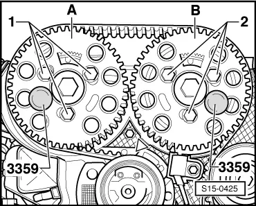
| –
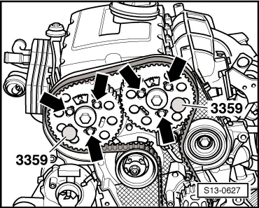
| Slightly screw in screws -arrows-. |
| l
| It must still be possible to turn the toothed belt sprockets on the hubs, however they must not hang loose. |
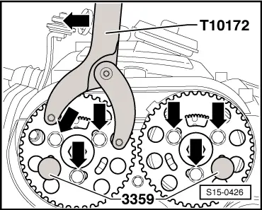
| –
| Turn toothed belt sprockets clockwise in the elongated holes as far as the stop. |
| –
| Fit toothed belt onto toothed belt sprocket of crankshaft, tensioning pulley, toothed belt sprockets, large guide pulley and, last of all, onto the toothed belt sprocket of the coolant pump. |
| Adjust the tension of toothed belt as follows: |
| –
| Loosen the fixing nut of the tensioning pully and pull the rig tool -T10265- out of the tensioning pulley. |
|
|
|
 Caution
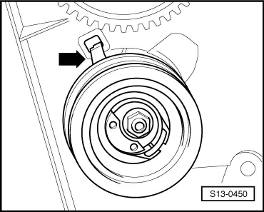
 Note
Note