
Octavia Mk2
| Removing and installing exhaust gas turbocharger for engine with engine identification characters BKD, AZV |

| 1 - | Gasket |
| q | replace |
| 2 - | to flap of radiator for exhaust gas recirculation |
| 3 - | 25 Nm |
| q | replace |
| q | Coat stud bolts with hot bolt paste -G 052 112 A3- |
| 4 - | Connecting tube |
| q | to flap of radiator for exhaust gas recirculation |
| 5 - | Support |
| q | for oil feed line |
| 6 - | 10 Nm |
| 7 - | Oil feed line |
| q | Check oil feed line for continuity before installing. |
| q | Fill the exhaust turbocharger with engine oil through the connection fitting of the oil feed line before installing |
| 8 - | Union nut - 22 Nm |
| 9 - | Connection fitting - 30 Nm |
| 10 - | Gasket ring |
| q | replace |
| 11 - | Gasket |
| q | replace |
| q | Check fitting position |
| 12 - | Exhaust gas turbocharger |
| q | can only be replaced complete with exhaust manifold and vacuum setting element of charge pressure control |
| q | removing → Anchor |
| q | installing → Anchor |
| q | Check vacuum setting element → Chapter |
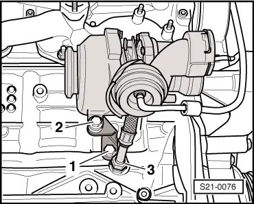
| 13 - | Support |
| q | between turbocharger and the cylinder block |
| 14 - | 40 Nm |
| q | first tighten all screws by hand |
| 15 - | Oil return line |
| q | in the cylinder block |
| 16 - | Connection fittings - 40 Nm |
| 17 - | 17 Nm |
| 18 - | 20 Nm |
| q | first tighten all screws by hand |
| 19 - | Heat shield |
| 20 - | 22 Nm |
|
 Caution
 Note
Note
|
|
|
|
|
|
|
|
|
|
|
|
Note
Note
|
|