skoda Workshop Repair Guides

Skoda Workshop Service and Repair Manuals

Removing and installing air filter for engine with engine identification characters BKD, AZV > < Pre-wiring for unit injectors and glow plugs - Summary of components for engine with engine identification characters BKD, AZV
Removing and installing pre-wiring for unit injectors and glow plugs for engine with engine identification characters BKD, AZV
Special tools and workshop equipment required
t  Key -T10310-
Removing
  Caution
The disassembly and assembly of the pre-wiring must only be performed by unscrewing and screwing the clamps. Slackening the cable guide from the clamps causes them to bend up and it can lead to cable fracture due to high play. This applies also when changing the unit injectors, as well as all work which does not require the complete removal of the pre-wiring.
–  Switch off the ignition and pull out the ignition key.
–  Remove cylinder head cover → Chapter.
   
–  Disconnect central plug conection at cylinder head. To do so, pull release pin in -direction of arrow 1- and open the knurled nut in -direction of arrow 2-.
  A15-0912
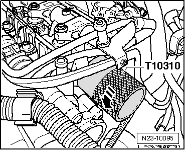
–  Position wrench -T10310- at adapter ring and slacken by a 90° turn (1/4 turn) in -direction of arrow-.
  N23-10095
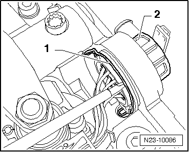
–  Pull the locking clip -1- slightly upwards using a screwdriver and press through central plug -2- to the inside.
  N23-10086
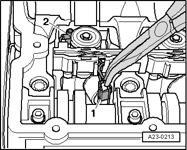
–  Disconnect plug connections -1- for the unit injectors, at the same time press latch clips together.
  A23-0213
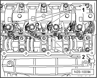
–  Unplug connector of the glow plugs -1-. Unscrew fixing screws -2- of stainless steel clamps and remove complete pre-wiring.
Install
Installation occurs in reverse order to removal. Pay attention to the following:
–  Position pre-wiring and tighten fixing screws to 10 Nm.
  N23-10094
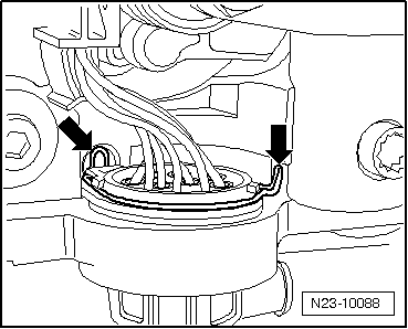
–  Guide the central plug through the opening in the bearing frame. To do so pay attention to the correct seating of the locking clip -arrows-.
  N23-10088
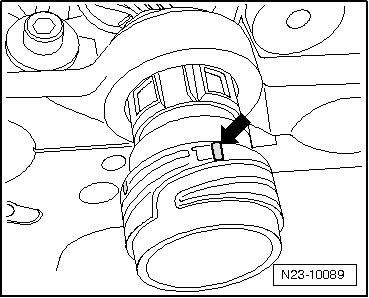
–  Position adapter ring (colour marked “long” leg -arrow- points to 12 o'clock).
  N23-10089
–  Position wrench -T10310- at adapter ring and interlock by a 90° turn (1/4 turn) opposite the -direction of arrow-.
  Note
After correct assembly of the adapter ring the colour marked “short” leg points to 12 o'clock.
–  Position central plug connection at cylinder head and lock.
–  Install cylinder head cover → Chapter.
  N23-10095

Removing and installing air filter for engine with engine identification characters BKD, AZV > < Pre-wiring for unit injectors and glow plugs - Summary of components for engine with engine identification characters BKD, AZV