skoda Workshop Repair Guides

Skoda Workshop Service and Repair Manuals

Principle circuit diagrams for different rinsing cycles > < Cleaning the refrigerant circuit with compressed air and nitrogen
Cleaning refrigerant circuit with refrigerant R134a (flush)
   
Cleaning refrigerant circuit with refrigerant R134a (flush)
l  In order to remove impurities (e.g. abrasion from defective compressor) as well as used refrigerant oil in a clean refrigerant-saving and environmentally friendly manner, without demanding installation, the refrigerant circuit is flushed out with refrigerant R134a or is blown through with compressed air and nitrogen.
The refrigerant circuit must be flushed with refrigerant R134a, if:
t  Dirt or other contaminations in the refrigerant circuit are present.
t  when evacuating a tight refrigerant circuit the vacuum gauge is not constant (there is humidity in the refrigerant circuit which builds up pressure).
t  the refrigerant circuit was open beyond standard assembly time (e.g. after an accident).
t  pressure and temperature measurements indicate that there is humidity in the refrigerant circuit.
t  There is a doubt about the oil volume in the refrigerant circuit.
t  the air conditioning compressor needed to be replaced because of internal damage (e.g. noise or no output).
t  required for the respective vehicle after replacing one of the components of the Workshop Manual.

Special tools and workshop equipment required
t  A/C service station with flushing system -VAS 6337- or -VAS 6380-. For these A/C service stations, the auxiliary function „flush refrigerant circuit with cooling medium R134a“ is available and the necessary flushing system for coolant circuit
t  Adapter set for passenger vehicles -VAS 6338/1-
   
Preliminary work
–  Drain refrigerant circuit.
–  Remove AC compressor → Heating, Air Conditioning → Rep. gr.87.
–  Replace catch pan/fluid reservoir with dessicator or only dessicator (specifically designed for vehicles) → Heating, Air Conditioning → Rep. gr.87 and reconnect together with cable. To do so, use the adapter and the filling hose -VAS 6338/31- from the adapter case of the motor car set.
–  Vehicles with expansion valve - remove expansion valve and install the adapter from the adapter case of the motor car set -VAS 6338/1- → Chapter.
–  Vehicles with throttle - remove throttle and always connect the refrigerant lines together.

Vehicles with expansion valve:
  Note
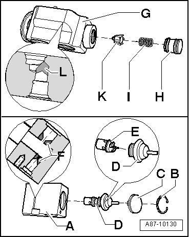
t  If no suitable adapter for the expansion valve, see → Chapter, can be found in the adapter case of the motor car set -VAS 6338/1-, the removed expansion valve can be drilled out and in this way it can be used instead of the adapter (in most cases the old expansion valve is replaced after the flushing of the refrigerant circuit and thus it is no longer needed).
t  During drilling operation, make absolutely sure that the sealing surfaces on the expansion valve are not damaged. The cooling medium could then leak when flushing.
   
t  Before drilling out, remove the control element and drill out the expansion valve with a suitable drill (drill diameter e.g. 6 mm).
t  The expansion valve is available in different versions with various designs. For the version -A- e.g. components -B-, -C- and -D- must be removed. Disconnect the component -E- (control element) from the component -D-. After this, use a suitable drill (diameter 6 mm) to drill out the expansion valve in range -F-.
t  Remove components -H-, -I- and -K-, pressure rod on the version -G- and after this, use a suitable drill (diameter 6 mm) to drill out range -L-.
t  Clean the drilled out expansion valve from machining residues (swarf).
t  Re-install components -B-, -C- and -D- on version -A- or component -H- on version -G-.
  A87-10130
Refrigerant
–  Check volume of refrigerant in the A/C service station, there must be at least 7 kg of refrigerant R134a.
–  30 mins before the first purging process or switching on the heating for the middle refrigerant bottle located in the service position (pressure in the middle refrigerant bottle increases) and before the first suctioning procedure switch off the heating again during the purging process.
–  Empty the container for the used oil of the A/C service station.
–  Connect the intake hose (high-pressure side) of the A/C service station to the low-pressure line which leads to the AC compressor with the aid of an adapter (cable with the larger diameter).
–  Connect return-flow hose (low-pressure side or suction side) of the A/C service station to the outlet of the flushing device for the refrigerant circuits.
–  Connect the inlet of the flushing system on the high pressure line to the AC compressor with the aid of an adapter (cable with smaller diameter).

  Note
t  Adapter for setting up the rinsing cycles (specifically designed for vehicles) → Chapter.
t  The components are always flushed through against the flow direction of the refrigerant when the air conditioning is in operation.
t  When flushing, impurities get out of the refrigerant circuit into the flushing device and are retained in the filters and dessicators installed there. Depending on the impurities, these components must be changed within short periods of time according to the operating instructions of the A/C service station or the flushing device for refrigerant circuits.
t  Depending on the type and intensity of the contamination of the flushed refrigerant circuit, the filter in the flushing device for refrigerant circuits must be replaced no later than after 5 to 10 flushing cycles (vehicles flushed thoroughly). If a very dirty refrigerant circuit is flushed out (the refrigerant oil from the refrigerant circuit is black and viscous or there is a lot of swarf in the refrigerant circuit) the filter is replaced after flushing the refrigerant circuit. If the refrigerant circuit is very dirty, it is also purposeful to once again flush the refrigerant circuit after changing the filter.
t  Depending on the type of the contamination, dirt deposits itself (used refrigerant oil and abrasion from the AC compressor) on the inspection glass or the inspection glasses of the flushing device for refrigerant circuits. Clean the inspection glass or the inspection glasses after flushing and flush the refrigerant circuit once again using a purging process for inspection.
t  The liquid refrigerant cannot be led through the expansion valve and the dessicator bag of certain fluid reservoirs with the required speed. These components must therefore be removed and replaced by adapters.
–  Switch on the A/C service station and flush the refrigerant circuit (a flushing cycle with three purging processes lasts approx. 1 to 1.5 hours).
  Note
t  The flushing of a refrigerant circuit must be performed according to the operating instructions of the A/C service station.
t  Depending on the version of the A/C service station, the container for the used oil contains approx. 125 cm3 of used refrigerant oil. If a system with a greater refrigerant oil volume must be flushed, it may be required to empty the used oil reservoir after the first purging process of a flushing cycle.
t  When flushing (up to minor residues can be neglected) the total refrigerant oil is washed out of the refrigerant circuit.
–  Observe the refrigerant which flows back out of the refrigerant circuit. Only when the refrigerant flows clear and completely colourless through the inspection glasses of the flushing device, the refrigerant circuit is clean.
   
The procedure of the purging process (the procedure is determined automatically according to the program of the A/C service station)
t  After switching on, the rinsing cycle is first of all evacuated and while doing so the refrigerant circuit is tested for leaks (depending on the version of the A/C service station, manually moving forward is perhaps required see → operating instructions of the A/C service station).
t  In the evacuated rinsing cycle, the corresponding specific volume of coolant (e.g. 4 kg) is filled in via the high-pressure side of the A/C service station (against the normal flow direction of the air conditioning and therefore on the low-pressure side of the refrigerant circuit of the vehicle). Depending on the version of the A/C service station, enough refrigerant is filled in until the rinsing cycle is completely filled with liquid refrigerant. This is determined in such a way that for a given period of time no more refrigerant can flow through.
t  After topping up with the determined volume of refrigerant, for example, the heating of the flushing device for refrigerant circuits is switched on depending on the version of the A/C service station and the flushing device for refrigerant circuits (only if the refrigerant is drained off in gaseous condition from the flushing device for refrigerant circuits).
t  After the refrigerant was drained off, the heating of the flushing device (if present) for the refrigerant circuits is switched off, the refrigerant circuit is again briefly evacuated depending on the version and after the evacuation, the refrigerant oil suctioned out of the refrigerant circuit is expelled out of the A/C service station.
t  The procedure, fill with refrigerant, drain off (and evacuate) is repeated twice (altogether it is performed three times).
After completing the purging processes:
–  Check the inspection glass or the inspection glasses of the flushing device. If dirty, clean the purging process in accordance with the operating instructions of the flushing system and once again perform a check of the purging process (it lasts only one purging process, about 30 minutes).
–  Remove the connections to the A/C service station from the refrigerant circuit of the vehicle (there must not be any overpressure present in the refrigerant circuit, if necessary briefly evacuate the refrigerant circuit once again).
–  Replace throttle and catch pan/fluid reservoir with dessicator or only dessicator (specifically designed for vehicles).
–  Vehicles with expansion valve - Check expansion valve, replace if dirty or corroded.
–  Depending on the fault:
l  Replace the AC compressor or unscrew the drain plug from the removed AC compressor (replace O-ring → Electronic Catalogue of Original Parts) and drain the remaining refrigerant oil. In order to speed up the evacuation of the refrigerant oil, turn the AC compressor with the clutch disk of the magnetic coupling by hand (disposal of used oil → Chapter). Subsequently fill the volume of new refrigerant oil, which corresponds to the refrigerant oil volume in the original part AC compressor, into the removed AC compressor → Heating, Air Conditioning → Rep. gr.87.

  Note
In the original part AC compressor there is a certain determined refrigerant oil volume.
–  Completely assemble again the refrigerant circuit, evacuate and fill.
–  Set the air conditioning again to operate and perform a functional test.
   

Principle circuit diagrams for different rinsing cycles > < Cleaning the refrigerant circuit with compressed air and nitrogen