Octavia Mk2
 Note
Note
|
 DANGER!
Note
|
|
|
|
|
|
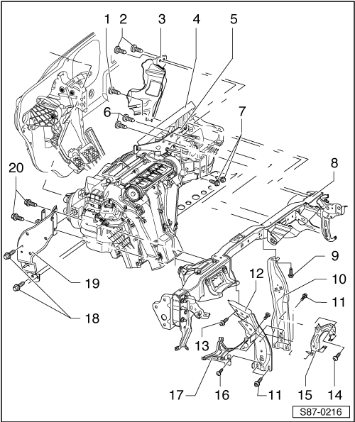
| 1 - | Screw, 4.5 Nm |
| 2 - | Screws, 4,5 Nm |
| q | 2 pieces |
| 3 - | Cable strap |
| 4 - | Air Conditioning |
| q | Removing: |
| – | Remove left footwell vent. |
| – | Remove the intermediate pieces for defrost duct and dash panel vents. |
| – | Disconnect the plug connections from the air conditioning unit. |
| – | Remove wiring loom from holder - Pos. 5. |
| – | Release screws - Pos. 6 and 7 - from holder - Pos. 5 -. |
| – | Remove holder - Pos. 5. |
| – | Remove the control unit for data bus diagnostic interface -J533- (attached in the area of the steering column to the bracket - Pos. 19 -) → Electrical System → Rep. gr.90. |
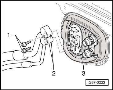
| – | Release screws - Pos. 1 and 2 - from cable clip - Pos. 3 -. |
Note| In order to reach the screw - Pos. 1 - the heater unit must be pulled out slightly from the front wall on the driver side. |
| – | Release screws - Pos. 18 and 20 - and remove from holder - Pos. 19 -. |
| Vehicles up to CW 44.08: |
| – | Remove holder - Pos. 15 and 17. |
| – | Remove supports - Pos. 10 and 12. |
| Vehicles as of CW 45.08 (MY 09 Facelift): |
| – | Remove the central pipe/dash panel - Pos. 8 → Body Work → Rep. gr.70. |
| All vehicles: |
| – | Remove the air conditioning unit. |
| q | Installing: |
| Installation is performed in the reverse order, pay attention to the following points: |
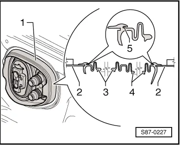
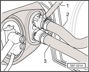
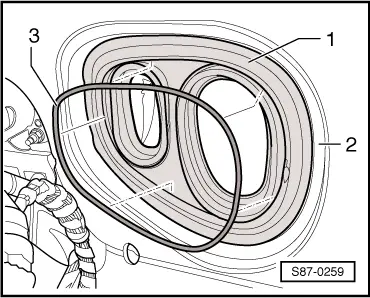
| – | First of all install the seal to the bulkhead from the passenger compartment and then guide the heat exchanger flange and the refrigerant connection through the seal → Fig.. |
| – | Pay attention to the fitting position of the seal → Fig.. |
| – | Attach the refrigerant lines to the expansion valve → Chapter. |
| – | Top up coolant → Engine → Rep. gr.19. |
| – | Fill the refrigerant circuit with the aid of the A/C service station. |
| 5 - | Bracket, right |
| 6 - | Screws, 8 Nm |
| 7 - | Screws, 8 Nm |
| 8 - | Module carrier |
| 9 - | Screws, 8 Nm |
| 10 - | Right support |
| q | As of CW 45.08 welded to the central pipe Pos. 8 |
| 11 - | Screws, 20 Nm |
| 12 - | Left support |
| q | As of CW 45.08 welded to the central pipe Pos. 8 |
| 13 - | Screws, 8 Nm |
| 14 - | Screws, 8 Nm |
| 15 - | Support |
| q | As of CW 45.08 welded to the supports Pos. 10 and Pos. 12 |
| 16 - | Screws, 2 Nm |
| 17 - | Support |
| 18 - | Screws, 8 Nm |
| 19 - | Bracket, left |
| 20 - | Screws, 8 Nm |
|
|