skoda Workshop Repair Guides

Skoda Workshop Service and Repair Manuals

Gearbox mechanics,operation, construction,diff. > < Preparing the installation of the clutch
Installing and adjusting the clutch
  Caution
Try to avoid removing or raising the plate support. Not even a little bit! The plates can turn.
  Note
t  The gearbox must be turned vertically in the assembly stand and the opening for the clutch must point upwards. Only in this way is it possible later on for the setting of the axial play of the clutch to be error-free.
t  It is important that the gearbox is clamped firmly in the assembly stand -MP9-101- → Chapter, it must not be turned.
t  
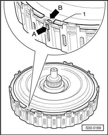
In the clutch the large plate support must be inserted in all plates, it must not have slipped out of the lowest plate.
t  The drive shaft of the gearbox oil pump is removed.
t  Do not install corrugated circlips.
Special tools and workshop equipment required
t  
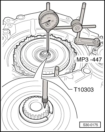
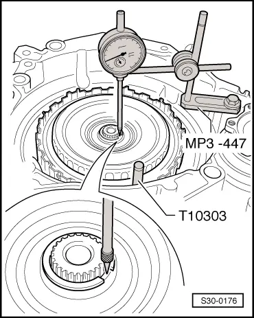
Universal dial gauge holder -MP3-447 (VW 387)-
t  
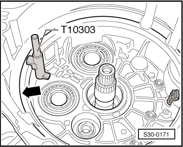
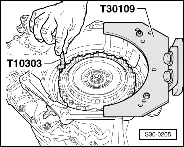
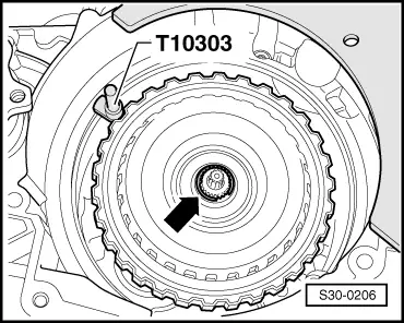
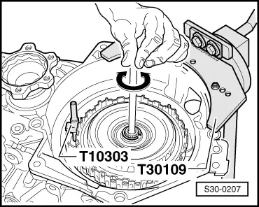
Retaining bolt -T10303-
t  
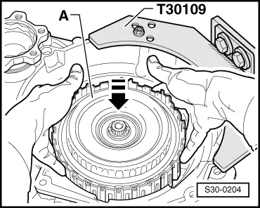
Gearbox mount -T30109 (VW 353)-
t  Gearbox mount -T30108-
t  Assembly stand -MP9-101-
t  Dial gauge
   
–  First put the retaining bolt -T10303- on the seat -arrow- of the clutch cover.
  S30-0171
–  Then carefully insert the clutch -A- in -direction of arrow-; do not let it fall in.
  S30-0204
The retaining bolt -T10303- must be held at the same time by a second mechanic.
The retaining bolt -T10303- remains there, until the clutch cover is installed.
  S30-0205
–  Determine from all supplied circlips the circlip with a thickness -arrow- of 2 mm and install it temporarily.
Before this circlip is removed again, two measurements must be carried out beforehand.
First measurement
l  The retaining bolt -T10303- remains installed!
–  Screw the universal dial gauge holder -MP3-447 (VW 387)- onto the gearbox flange.
  S30-0206
–  Position the push-button of the dial gauge on the drive shaft of the gearbox.
–  Set the dial gauge to 0 with 1 mm bias.
–  Lift the clutch upwards up to the stop and note the measuring result.
Second measurement
l  The retaining bolt -T10303- remains installed!
  S30-0175
–  Position the push-button of the dial gauge on the hub of the large plate support of the clutch.
  Note
Push-button must not be positioned on the circlip.
–  Set the dial gauge to 0 with 1 mm bias.
–  Lift the clutch upwards up to the stop and note the measuring result.
Now it is calculated, which one from all nine circlips will finally be installed
–  For this purpose use this formula:
   Second measurement minus first measurement plus 1.85 mm = thickness of the circlip to be installed.
Example:
  S30-0176
 0.12 mmsecond measurement 
0.04 mm first measurement 
+1.85 mmconstant value 
= 1.93 mmMeasuring result 
Thickness of the circlip 1.9 mm

–  Please note this result.
The remaining nine circlips are classified in 0.1 mm jumps.
–  Measure all the circlips and determine the circlip, which corresponds the closest to your result.
–  Remove the 2 mm thick circlip and replace with measured circlip.
–  Dispose of all the remaining rings.
  Note
Ciclips must only be installed once.
   
–  Insert the drive shaft of the gearbox oil pump and to do so turn slightly -in direction of arrow-.
  S30-0207
–  Insert the clutch cover in such a way that the peg -arrow B- is aligned with the marking -arrow A-.
–  Insert new circlip -1- into the clutch.
–  Remove retaining bolt -T10303-.
–  Install clutch cover → Chapter.
The installation is completed, the clutch is correctly set.
After installing the gearbox
–  Carry out the basic measurement of the mechatronics for double clutch gearbox DSG -J743- using the → Vehicle diagnostic tester.
  S30-0169

Gearbox mechanics,operation, construction,diff. > < Preparing the installation of the clutch