skoda Workshop Repair Guides

Skoda Workshop Service and Repair Manuals

Install gearbox (Octavia II) > < Removing gearbox, front-wheel drive (Octavia II)
Removing gearbox, four-wheel drive (Octavia II)
  Note
t  Observe instructions for automatic gearbox DSG - 02E → Chapter.
t  General repair information → Chapter.
t  Regulations concerning cleanliness when working on the gearbox → Chapter.
t  All cable straps which are detached or cut open when removing, should be fitted on again in the same place when installing.
t  If the battery earth strap is disconnected and connected, carry out additional operations → Electrical System; Rep. gr.27.
Special tools and workshop equipment required
t  
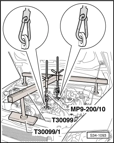
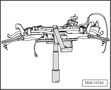
Supporting device -T30099-
t  Surface -T30099/1-
t  Hook -MP9-200/10-
t  
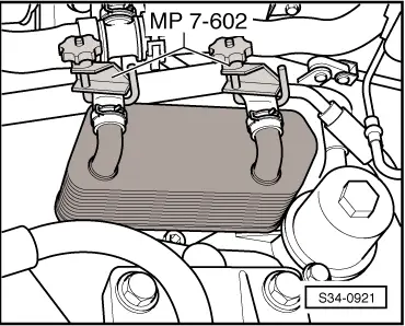
Hose clamp -MP7-602 (3094)-
t  Gearbox mount -3282-
t  Bolt -3282/29-
t  
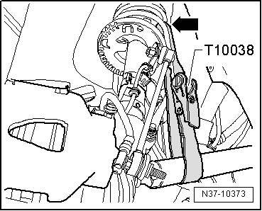
Tensioning strap -T10038-
t  
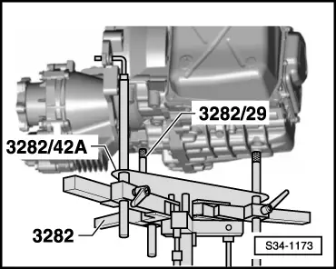
Adjusting plate -3282/42A-
t  Engine/gearbox jack, e.g. -V.A.G 1383 A-
t  Pliers for spring strap clips, e.g. -VAS 6340-
t  
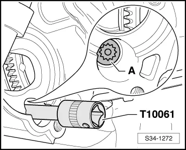
Socket insert, e.g. -T10035- or socket insert XZN 14 -T10061-
t  High-temperature grease -G 052 133 A2-
t  Grease -G 000 100-
–  Shift selector lever into position „P“.
–  Disconnect the battery-earth strap with the ignition off → Electrical System; Rep. gr.27.
–  Remove engine cover → engine; Rep. gr.10.
–  Remove air filter → Engine; Rep. gr.23.
–  Remove battery and battery tray → Electrical System; Rep. gr.27.
–  Remove the cooling water tank cover → Body Work; Rep. gr.66.
   
–  Release lock washer -1- and remove to the top.
–  Remove lock washer -3- towards the top.
–  Press off the selector lever control cable -2- from the lever/gearshift shaft in -direction of arrow- and slightly press out of the cable support towards the rear.
  Note
t  The lock washer for the selector lever control cable -3- and the lock washer -1- must always be replaced → Electronic Catalogue of Original Parts.
t  Do not bend or buckle the selector lever control cable.
t  The selector lever control cable is guided out of the cable support when removing the gearbox.
  S34-0916
t  If the lock washer cannot be removed without damaging the selector lever control cable, it is also possible to remove the cable support -2- (unscrew screws -1-).
  A37-10705
–  Pull back the protective collar and unscrew the cable -1- at the solenoid switch of the starter.
–  Separate the plug connection -2- at the solenoid switch of the starter.
–  Remove the earth lead -3- from the fixing screw of the gearbox console.
  Caution
Under no circumstances must the plug contacts in the plug of the gearbox be touched with the hands, because the control unit can be destroyed through static discharge as well as the mechatronics.
–  Grab with the hand (without gloves) at the mass, in order to discharge yourself electrostatically.
–  Unlock the cap of the plug -4- by turning it to the left and disconnect the plug from the gearbox.
–  Remove the screws from the starter and take them off.
  S34-0937
–  Unscrew all connecting screws of the engine/gearbox -1, 2 and 4- accessible from the top. To this end, use if necessary the socket insert -T10035-.
The screws -3 and 5- attach the starter at the gearbox.
  Note
  S34-1092
The screw Pos. 4, which is marked as -A- in the fig., is located in the starter opening and is only accessible after removing the starter. Screw out this screw using the socket insert XZN 14 -T10061-.
  WARNING
Hot steam may escape after the compensation bottle is opened. Cover the cap with a cloth and open carefully.
–  When the engine is warm the cooling system is under pressure. Slowly open the cap of the compensation bottle, in order to first reduce pressure before pulling off the coolant hoses.
–  Do not place fluffing cloths on the gearbox oil cooler and the gearbox, in order to collect flowing out coolant.
–  Mark the coolant hoses to the gearbox oil cooler in order to prevent interchanging when installing.
  S34-1272
–  Pinch off coolant hoses with hose clamps -MP7-602 (3094)- and remove hoses from gearbox oil cooler.
–  Close gearbox oil cooler with a clean plug.
  S34-0921
–  Unscrew screw -1- from rear intake hose -3- and release pipe -2- from secondary air injection system and disconnect.
  S34-0933
–  Remove bracket of coolant pipes and fuel. To do so release screws -1-.
–  Remove fuel hose -2- on the tandem pump. Collect escaping fuel with a cloth.
–  Close fuel hose -2- of tandem pump with a clean plug.
–  Unscrew screws -3- and -5- and remove bracket -4-.
  S34-0934
–  Mount the support fixture -T30099- on the spring domes.
–  Hang the spindles of the support fixture on the left and right engine lifting eye.
–  Pre-tension the engine with the spindles, do not raise.
–  Loosen the wheel bolts on front left and front right.
–  Raise vehicle → BookletOctavia II.
–  Remove wheels at the front.
–  Remove the sound dampening system → Body Work; Rep. gr.50.
  S34-1093
–  Release screws -1- to -3- and remove the complete cover of the left wheelhouse liner.
  S34-0939
–  Unscrew nuts -2- from bracket -1- on the oil pan and remove bracket from the threaded bores at the oil pan.
  Note
t  The threaded bores are welded at the front of the gearbox to the oil pan.
t  Unscrew the lower nut from below, after the noise insulation was removed.
  S34-0907
–  Remove the air guide hose -2-. To do so slighty raise the retaining clips -1- and pull the air guide hose from the pipes.
  S34-0940
–  Remove the air guide hose on the right. To do so slighty raise the retaining clips -arrows- and pull the air guide hose from the pipes.
  S34-0941
–  If fitted, remove protection plate -A- at the gearbox -arrows-.
  S34-0905
–  Disconnect plug connection -1-.
–  Release screws -arrows- and take out the fan shroud downwards → Engine; Rep. gr.19.
  S34-0868
–  Unscrew screw -1- and remove small cover plate -2- for flywheel.
–  Remove all supports for exhaust gas system from gearbox and from exhaust pipe → Engine; Rep. gr.26.
  S34-0955
–  Separate exhaust system at the clamping sleeve and remove bracket for the exhaust system from the assembly carrier -arrows- → Engine; Rep. gr.26.
–  Tie up pre-exhaust pipe.
  Note
The decoupling element in the pre-exhaust pipe should not be bent by more than 10° - risk of damage.
  A26-10131
–  Mark the position of the propshaft with flexible disk to the output flange of the angle gearbox.
–  Unscrew the propshaft with flexible disk from the output flange of the angle gearbox -arrows-.
  S34-0970
–  Release plug -1- from oil level and oil temperature sender -G266- and loosen the wiring loom from the bracket -2- (if present).
  S34-0943
–  Remove pendulum support from gearbox, to do so release the bolts -arrow B- and -arrow C-.
  Note
Do not release screw -arrow A-. The pendulum support is removed together with the assembly carrier.
  S34-0882
–  If present, disconnect the electrical plug connection -2- at front left vehicle level sensor -G78-.
–  Release screw -1-.
–  Fix the assembly carrier before removing → Chassis; Rep. gr.40.
  Note
If the assembly carrier is not fixed, an axial measurement must later be carried out.
  S34-0945
–  Remove the assembly carrier with pendulum support, both track control arms and steering → Chassis; Rep. gr.40.
  Note
  N34-10720
After removing the pendulum support from the gearbox, the engine/gearbox unit swivels slightly towards the front (direction front). When removing and installing make sure that the gasket ring -arrow- in the flange of the propshaft is not damaged.
–  Push engine/gearbox unit forwards and pull off the propshaft from the output flange of the angle gearbox.
–  Tie up propshaft.
Vehicles with diesel particle filter
–  Remove particle filter with bracket for particle filter → Engine; Rep. gr.26.
Continued for all vehicles
  S39-0359
–  Remove heat shield for right drive shaft from angle gearbox -arrows-.
–  Removing the left and right drive shaft from the gearbox → Chassis; Rep. gr.40.
  N34-11224
–  Tie up the right drive shaft as far as possible and place the left drive shaft to the rear and secure (while doing so do not damage the surface protection).
  N37-10373
–  Release screws -1- from gearbox mount -A- at angle gearbox.
–  Only slacken the screws -2- and -3- of the gearbox mount at the engine.
  Note
t  The screw -3- cannot be fully released as it touches the right flange shaft -B-.
t  The gearbox mount can only be removed if the gearbox is removed from the engine.
  S34-1277
–  Screw out screws -1- and -2-.
–  Lower the engine/gearbox assembly alternately at the spindles of the support fixture -T30099- by 4 turns.
–  Remove console -A-.
  S34-0946
–  Lower the engine/gearbox assembly alternately at the spindles of the support fixture -T30099- uniformly, until the dimension -a- is adjusted between the gearbox housing and the gearbox mounting.
l  Dimension -a- = 100 ... 110 mm
For the removal of the gearbox 02E the gearbox mount -3282- is aligned with the adjusting plate -3282/42A - and placed on the engine/gearbox jack -V.A.G 1383 A-.
  S34-0947
–  Align arms of the gearbox mount to match the holes in the adjusting plate -3282/42A-.
–  Screw in the mounting elements as shown on adjusting plate -3282/42 A-.
–  Position the engine/gearbox jack -V.A.G 1383 A- below the vehicle.
l  The arrow symbol on the adjusting plate -3282/42 A- points in the direction of travel.
–  Align the gearbox mount -3282- parallel to the gearbox.
–  Screw the bolt -3282/29- into the gearbox.
–  Attach the two other support elements at the gearbox, as shown in the illustration.
–  Secure the gearbox with tensioning strap -T10038- to the gearbox mount -3282-.
–  Position the gearbox by lifting the engine/gearbox jack -V.A.G 1383 A- from the bottom.
  S34-1173
–  Unscrew the connecting screw of the engine/gearbox -arrow- next to the angle gearbox (Pos.10 fig. S34–1092).
  S34-1224
–  Unscrew the remaining connecting screws -6…9- engine to gearbox.
–  Press the gearbox out of the dowel sleeves -A- of the engine.
–  Pull off the gearbox from the engine by approx. 30 mm.
  S34-1092
–  Unscrew gearbox mount -A- from engine -arrows- and remove.
–  Carefully swivel gearbox towards the left frame side rail.
–  Lower the gearbox carefully and slightly with the engine/gearbox jack -V.A.G 1383 A-.
–  Change the gearbox position at the spindles of the gearbox mount -3282- when lowering.
–  When lowering the gearbox, guide the selector lever control cable out of the cable support.
  Note
t  Observe all lines and coolant hoses when lowering the gearbox.
t  Do not bend or buckle selector lever control cable.
Transport the gearbox and secure it to the assembly stand → Chapter.
  S34-1273

Install gearbox (Octavia II) > < Removing gearbox, front-wheel drive (Octavia II)