
Octavia Mk2
 Note
Note| t | The two-piece propshaft is installed until 27.05.07. The front propshaft pipe Pos. 5 can be separated from the rear propshaft pipe Pos. 19. |
| t | During the manufacture, the entire propshaft is balanced, in order to obtain the smoothest running possible. The balancing of the entire propshaft or the individual propshaft pipes is not possible with workshop tools. It is therefore essential to always replace the entire propshaft in case of damage to the front or the rear propshaft pipe. |
| t | Do not bend the propshaft, only store extended and transport. |
| t | Before the removal, mark the position of all parts to each other. Carry out the installation again in the same position, otherwise the imbalance is too great, damages to the bearing and humming noises could occur. |

| 1 - | Angle gearbox |
| 2 - | 50 Nm + torque a further 90° |
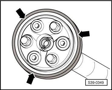
| q | always replace → Electronic Catalogue of Original Parts |
| 3 - | Flexible disk with heat shield |
| q | Fitting position: The open side of the heat shield faces towards the gearbox |
| 4 - | 60 Nm |
| q | Assignment → Fig. |
| 5 - | Front propshaft pipe |
| q | when installing and removing do not damage the centering bushing and gasket ring in the middle of the flange |
| 6 - | 40 Nm |
| 7 - | Shim |
| 8 - | Open warm-type clamp |
| q | tensioning → Fig. |
| 9 - | Joint boot for CV joint |
| q | drive out with drift pin before pressing off the CV joint |
| q | check for damage |
| 10 - | Disc spring |
| q | interlocked at inside diameter |
| q | Fitting position: large diameter lies on the CV joint |
| 11 - | Gasket |
| q | always replace (pull off protective foil and stick in joint) → Electronic Catalogue of Original Parts |
| 12 - | CV joint |
| q | pressing off → Fig. |
| q | pressing on → Fig. |
| q | Grease filling: Push 25 g grease on each side (total 50 g) into the joint. Grease joint if necessary, when replacing the joint boot. |
| 13 - | Circlip |
| q | always replace → Electronic Catalogue of Original Parts |
| q | removing and installing with circlip pliers |
| 14 - | 45 Nm |
| 15 - | Washer |
| q | always replace → Electronic Catalogue of Original Parts |
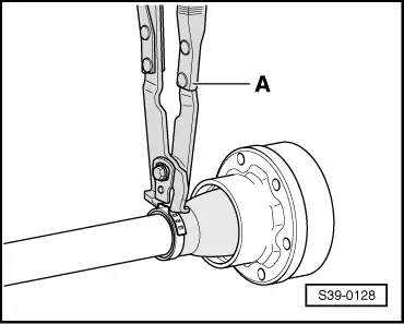
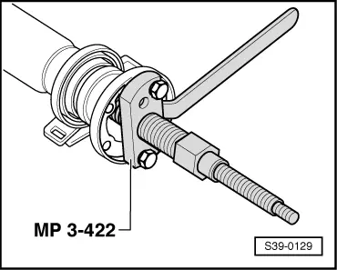
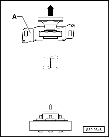
| 16 - | Flange |
| q | remove → Fig. |
| q | installing → Fig. |
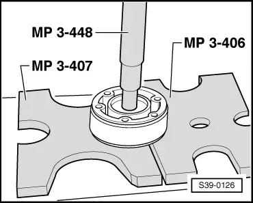
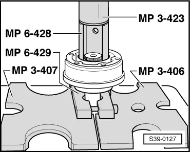
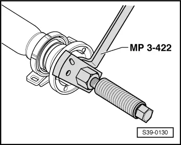
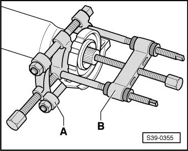
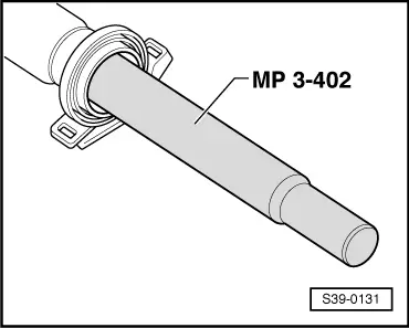
| 17 - | Intermediate bearing |
| q | remove → Fig. |
| q | Fitting position → Fig. |
| q | drive in → Fig. |
| 18 - | 25 Nm |
| q | attaches additionally the heat shield |
| 19 - | Rear propshaft pipe |
| q | when installing and removing do not damage the centering bushing and gasket ring in the middle of the flange |
| 20 - | 60 Nm |
| q | Assignment → Fig. |
| 21 - | Balancing nut |
| q | not fitted to all propshafts |
| q | if the collar screw Pos. 23 was detached, the balancing nut and the balancing washer Pos. 22 must not be installed again |
| 22 - | Balancing washer |
| q | not fitted to all propshafts |
| q | if the collar screw Pos. 23 was detached, the balancing nut and the balancing washer Pos. 21 must not be installed again |
| 23 - | 50 Nm + torque a further 90° |
| q | always replace → Electronic Catalogue of Original Parts |
| 24 - | Flexible disk with oscillation damper |
| q | Fitting position → Fig. |
| 25 - | Rear final drive |
|
|
|
|
|
|
|
|
|
|
|
|
|
|
|
|
|
|
|
|
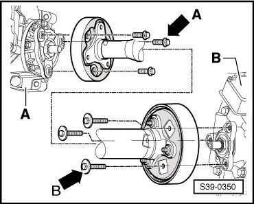
| Collar screw with | Fitting location |
| small collar -arrow A- | Propshaft on front final drive -A- |
| large collar -arrow B- | Propshaft on rear final drive -B- |