skoda Workshop Repair Guides

Skoda Workshop Service and Repair Manuals

Repairing gearbox housing > < Disassembling gearbox
Assembling gearbox
Assembling gearbox
l  A new grooved ball bearing must be pressed onto the drive shaft → Chapter.
   
Gearbox up to 05.09
–  Insert the drive shaft -1-, the output shaft 5th/6th gear -2- together with gear shift rod -3-, shift fork -4- and reverse shaft -5-.
  S34-0860
Gearbox as of 06.09
–  Place the reverse gear shift fork -4- on the 5th/6th gear shift rod -3- in its installed position → Anchor.
–  Insert the drive shaft -1-, the output shaft 5th/6th gear -2- together with gear shift rod -3-, shift fork -4- and reverse shaft -5-.
l  The shift gate -arrow A- of the reverse gear shift fork points to the outer side of the gearbox. The shift gate -arrow B- of the 5th/6th gear shift rod must point to the inner side of the gearbox.
Continued for all gearboxes
  S34-1230
–  Insert differential gear -1-.
–  Take the output shaft gears 1 through 4 -3- with the gear shift rods -4- in the right hand as shown.
–  Slightly lift the differential gear with the left hand.
–  At the same time the 2nd mechanic lifts the drive shaft, the output shaft 5th/6th gear and reverse gear -2- together with the reverse shaft.
–  Insert the output shaft gears 1 through 4 in -the direction of the arrow-.
The serrations of the drive shaft, output shafts and final drive/differential gear must be in mesh.
–  Place the shafts and the differential gear in their bearing assembly.
  S34-0861
–  Secure the supporting bridge -MP3-425- for drive shaft to the clutch housing.
  Note
To provide a clearer illustration, the clutch housing is shown at an angle of 180°.
–  Screw in screw -A- until the drive shaft is lifted slightly.
  S34-0845
The grooved ball bearing/drive shaft only fits in one position in the gearbox housing
One flattened part is located at the grooved ball bearing/drive shaft and at the bearing support for the grooved ball bearing in the gearbox housing.
l  If the flattened parts -A- and -B- are present, a washer must not be inserted above and below the grooved ball bearing/drive shaft → Chapter.
l  The flattened parts -A- at the grooved ball bearing and at the bearing support -B- must be aligned in the gearbox housing.
–  Mark these flattened parts in different colours.
–  Transfer the markings onto the upper area of the grooved ball bearing and onto the upper area of the bearing support of the gearbox housing (⇒ next figure).
–  Heat the gearbox housing with the hot-air blower in the area of the bearing assembly for grooved ball bearing/drive shaft to 100°C for approx. 10 minutes.
  Note
t  Warming up is necessary so that the grooved ball bearing is not damaged when installing the gearbox housing.
t  Apply sealant -AMV 188 200 03- uniformly on the sealing surface of the clutch housing.
  N34-11101
t  Align the marking of the grooved ball bearing -A- to the marking on the gearbox housing -B- and position gearbox housing.
  N34-11102
–  Tighten new screws -A-, -B- and -C- for the gearbox housing at the clutch housing to tightening torque.
Assignment of screws:
A - Screw with captive washer
B - Screw without washer
C - Screw with captive washer
  N34-10565
–  Install circlip -1- for grooved ball bearing/drive shaft.
–  Remove supporting bridge -MP3-425- for drive shaft.
–  In case the serrated sleeve for the gearshift shaft was removed, drive it in with the drift → Chapter up to the stop of the tool.
–  Turn the gearbox with the opening for the gearshift shaft in the assembly stand upwards.
  S34-0832
–  Insert the gearshift shaft -1- into the bottom bearing -2- and into the gearshift forks -3-. The cap in the illustration is removed for purposes of clear presentation.
  S34-0862
–  Press the gearshift shaft -1- against the serrated sleeve -2--direction of arrow- and guide with the shift finger -3- through the gearshift forks up to the stop downwards.
l  The gearshift cover -4- must be positioned at the same time parallel to the screw-on surface at the gearbox housing.
l  The gearshift shaft must slide easily into the selector movement (upwards and downwards).
  Note
If the gearshift cover is positioned obliquely to the screw-on surface, the gearshift shaft is not inserted into the bottom bearing.
  S34-0863
–  Tighten screws -3- for the cover/gearshift shaft -4-.
–  Screw in locking screw -2-, at the same time the locking angle -arrow- must be laid out.
–  Install switch for reversing lights -F4--1-.
Gearbox with start-stop system
  S34-0858
–  Install transmission neutral sender -G701--arrow-.
Continued for all gearboxes
  N34-11292
–  Install left flange shaft with pressure spring, stop disc and conical ring.
Front-wheel-drive
–  Install right flange shaft with pressure spring, stop disc and conical ring.
Continued for all gearboxes
  A39-0360
–  Drive in the gasket ring for the drive shaft.
–  Install slave cylinder with release bearing → Chapter.
–  Shift through all gears consecutively.
  S34-0865
–  Drive the cap into the gearbox housing up to the stop.
  N34-11105
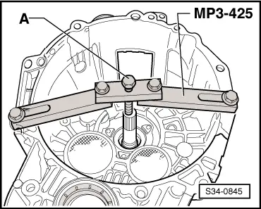
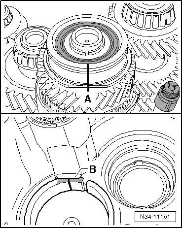
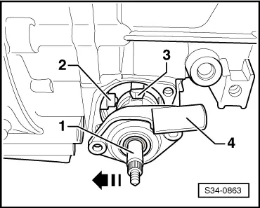
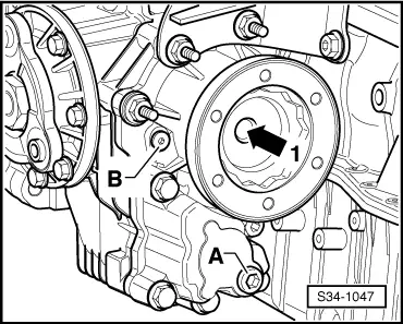
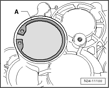
–  Secure cap with circlip -A-.
–  Remove gearbox from assembly stand.
Four-wheel drive
Install angle gearbox as follows at the manual gearbox:
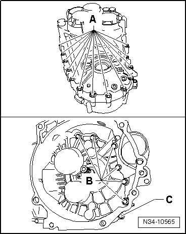
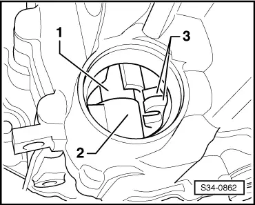
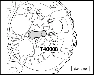
–  On manual gearbox, lightly grease the rigid serration at differential gear with grease for the plug serration of the clutch disc - G 000 100-.
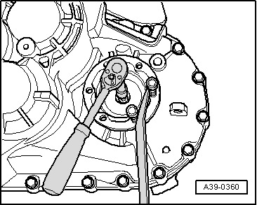
–  Push angle gearbox fully onto the manual gearbox, while doing so slowly turn the flange shaft (carefully press angle gearbox onto gearbox up to stop).
  Note
t  
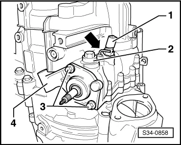
Do not pull angle gearbox with the fixing screws against the manual gearbox, otherwise the angle gearbox can tilt and the fixing eyes can break off.
t  Tighten gearbox/angle gearbox connecting screws crosswise (always replace screws → Electronic Catalogue of Original Parts).
–  Attach angle gearbox to gearbox and tighten connecting screws crosswise to tightening torque → Chapter Pos. 17.
  N34-11100
–  Tighten the screw of the flange shaft -arrow 1- with socket insert -T10107A- to tightening torque → Chapter Pos. 16.
  S34-1047

Repairing gearbox housing > < Disassembling gearbox