
Octavia Mk2
|
|
|
|
|
 Note
Note
|
|
|
|
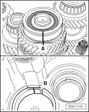
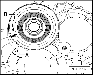
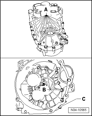
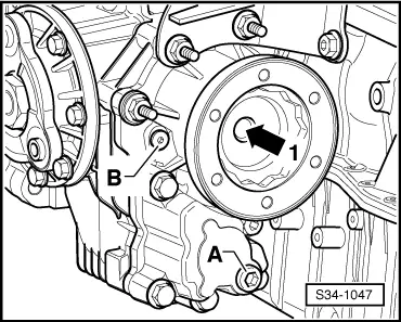
| Grooved ball bearing for the drive shaft and the gearbox housing | ||
| No flattened parts at the grooved ball bearing -A- and at the bearing support -B- → Anchor | ||
| Flattened parts at the grooved ball bearing -A- and at the bearing support -B- → Fig. |
|
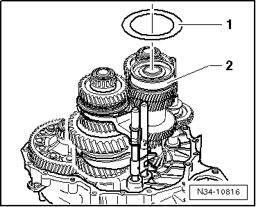
| Top washer | Outer diameter | 78.6 mm |
| Bottom washer | Outer diameter | 85 mm |
|
|
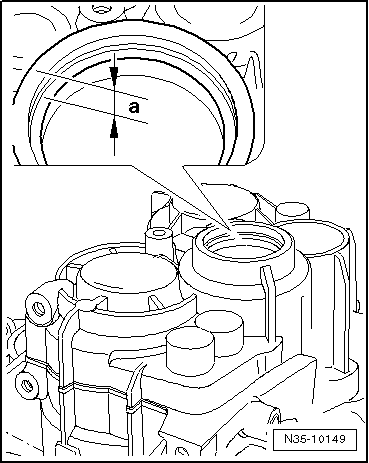
| Shoulder above the grooved ball bearing | Dimension „a“ | Top washer |
| up to production date 19.03. 06 | 10 mm | no |
| as of production date 20.03. 06 | 10.7 mm | yes |
|
|
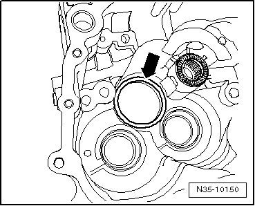
| Area below the bearing pedestal | Bottom washer | |
| up to production date 19.03. 06 | not chamfered | no |
| as of production date 20.03. 06 | chamfered slightly deeper | yes |
|
|
|
|
|
|
Note
|
|
|
|
|
|
Note
|
|
|
|
Note
|
|
|
|
Note
|
|
|
|