
Octavia Mk2
|
 Note
Note
|
|
|
|
|
|
|
|
|
|
|
|
|
|
|
|
|
|
Note
|
|
|
|
|
|
|
|
|
|
|
|
|
|
|
|
|
|
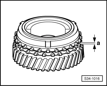
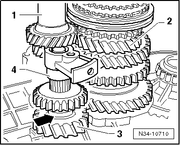
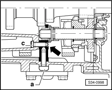
| Clearance -a- | Fitting dimension | Wear limit |
| 5th/ 6th gear | 1.1 ... 1.7 mm | 0.5 mm |
|
|
|
|
|
Note
|
|
|
|
 WARNING
Note
|
|
|
|
Note
|
|
|
|
|
|
|
|
|
|
|
|
|
|
|
|
|
|
Note
|
|
|
|
|
|